|
December 14, 2010
The Warbler, a
true pitch shifting vibrato unit for guitar
 Ever since I restored the Maggie M10-A, I've been
intrigued with the pitch shifting vibrato idea. Then in September of 2010, forum
member Merlin posted some info on a Wurlitzer organ vibrato circuit. That got me
thinking, "What's going on with the old Hammond organ vibratos?" I've seen many
of the vibrato units on eBay for cheap! Maybe it could be converted to guitar
use. What an original idea! WRONG! As I started web crawling, looking for info,
I quickly found a guy that had already done this. Just proves again, there
really ain't any more original tube guitar amp ideas. Oh well. I still want to do
it, so I started watching eBay for an affordable unit. Many sellers are parting
out organs and are almost giving these 'useless' units away after they sell the
more popular power amps. Some even have tubes included. I picked up my AO-41
from eBay for $5.00. What the heck! I got a couple of AO-47s too. If this idea
becomes popular, the price is gonna go up. Ever since I restored the Maggie M10-A, I've been
intrigued with the pitch shifting vibrato idea. Then in September of 2010, forum
member Merlin posted some info on a Wurlitzer organ vibrato circuit. That got me
thinking, "What's going on with the old Hammond organ vibratos?" I've seen many
of the vibrato units on eBay for cheap! Maybe it could be converted to guitar
use. What an original idea! WRONG! As I started web crawling, looking for info,
I quickly found a guy that had already done this. Just proves again, there
really ain't any more original tube guitar amp ideas. Oh well. I still want to do
it, so I started watching eBay for an affordable unit. Many sellers are parting
out organs and are almost giving these 'useless' units away after they sell the
more popular power amps. Some even have tubes included. I picked up my AO-41
from eBay for $5.00. What the heck! I got a couple of AO-47s too. If this idea
becomes popular, the price is gonna go up.
This project is based on the Hammond AO-41 vibrato unit. The AO-47 is
almost identical to the AO-41.
It could have been used just as easily as the AO-41. Here's the original schematics and theory of operation.
The theory is for the AO-41 circuit, but holds true for the AO-47 as well.
Hammond_AO-41_and_AO-47_Vibrato_Units.pdf (857K)
I began by adding wires for B+ and filaments and verifying
the unit worked. It did! Next I added a pot bracket and replaced the original
fixed frequency phase shift oscillator with the Fender 6G16 oscillator circuit
and a range switch. The range switch provides two overlapping frequency ranges
for a 2.8Hz to 10.5Hz overall frequency range. The AO-41 plate driven driver was
replaced with the AO-47 cathode driven driver. This allowed the entire osc/driver
circuit to be handled by a single 12DW7 tube. The modulator circuit was left
intact. I adapted the input/output circuits to connect into a guitar amp's FX
loop. All tweaks were made on this prototype assembly.
The prototype worked very well. The vibrato effect can be
subtile or deep and lush, slow or fast. Sounds good either way. It does kill a
little of the glassy high end tone of my amps. I may be able to tweak that
later although it's not really a problem for me. Glassy twang ain't really meant for
vibrato. So, I'm off to the computer to draw the final schematic and develop a
layout.
During the drawing process I decided
to make this a stand-alone vibrato unit, rather than rely on an FX loop, since
several of my amps don't have FX loops. So I added an input and output amp
stage. I later discovered the output stage was not required. There's a link to
my final schematic and layout at the bottom of this page.
Update 02/18/2013
Revision 2. What began as a simple mod to provide a
LED front panel indicator for the vibrato LFO turned into a major overhaul.
Read all about it on the Warbler Revision 2
page.
Update 12/24/2010
Revision 1. I removed the output gain stage circuitry
since it was not needed. But more important, I replaced the output level
control with a mixer control. Now you can blend the dry signal with the
vibrato signal. This produces a big variety of nice sounds ranging from near
tremolo, to phaser-like, to vibrato. The Warbler is now much more versatile.
I also experimented with blending different phase
shift stages together, similar to the circuit on this web page...
http://www.solorb.com/elect/musiccirc/liquidator1/
...but I settled for the revision 1 circuit, buttoned
it up, and called it done. The Warbler has plenty of tone variety and the 4
knobs will keep most twiddlers happy for a long time.
Enough talking. Here are some short sound clips to give
you an idea of the sound.
And here's the eye candy...
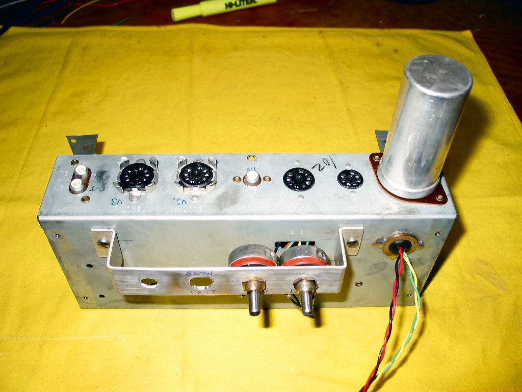
Prototype. Most of the experimenting was done on this Hammond AO-41 vibrato unit
which has been modified for use with a guitar amp's FX loop. B+ and filaments
were supplied from my Matchless Lightning amp.
The left end of the board was modified to use the Fender
6G16 tremolo oscillator to drive the vibrato modulator circuit. The saturable
reactor transformers have already been
removed at this time to be used in the actual build.
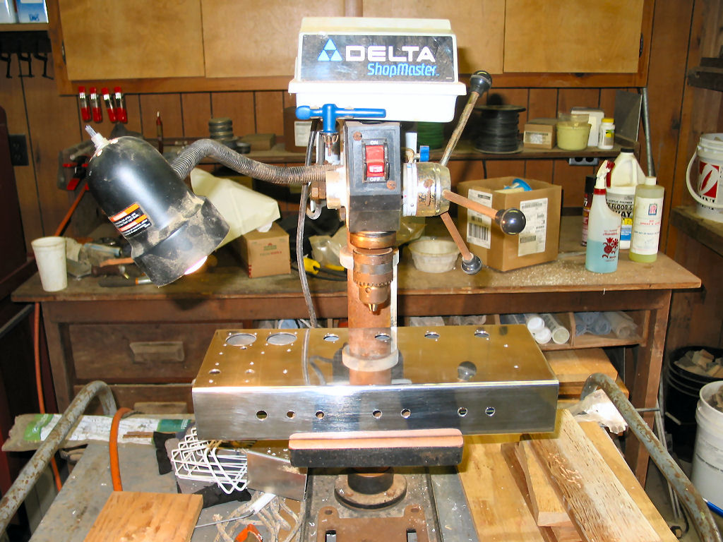
The 16" x 6.5" x 2.5" chassis is 99% drilled and ready for polishing.
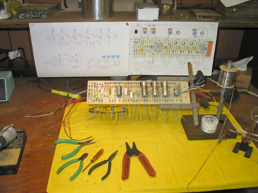
Components are loaded and all board interconnecting wires are in place and are
being trimmed to length, stripped, and tinned. This involves dry fitting into the
chassis several times to get the wire lengths right. Stripping and tinning
teflon insulated wire is much easier outside the chassis.
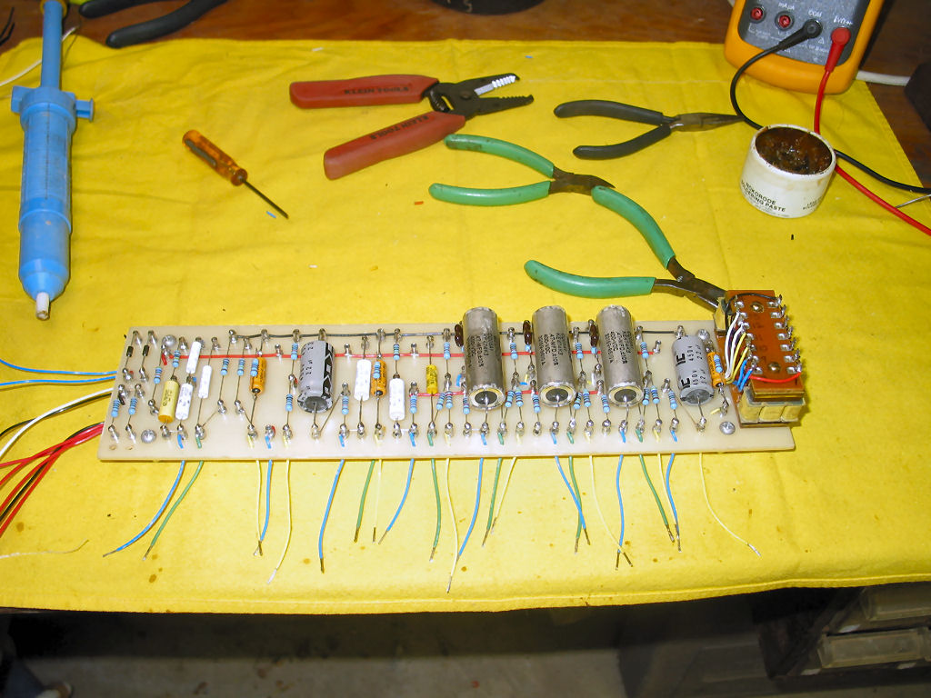
All wires are prepared and the saturable reactor transformer is installed. The board is
ready for final installation into the chassis. Nominal value B+ dropping resistors will
be installed temporarily to determine actual values, before permanent
installation. I know the node voltages I'm looking for and since I'm using
parallel nodes, it's easier and quicker to just determine actual resistor
values by substitution.
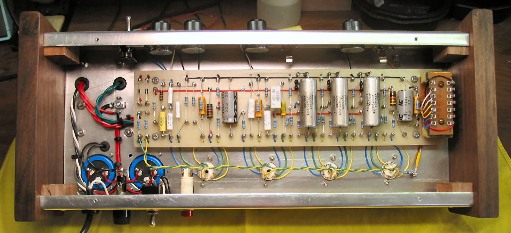
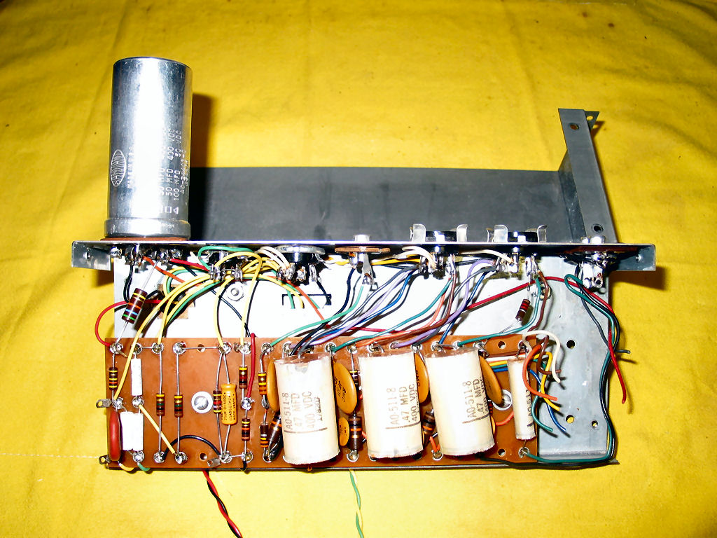
Here's a gut shot of the completed unit. This board design went through more
revisions than any of my previous projects. This is the first time I've
wired filaments 'Fender' style.
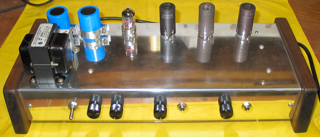
...and a topside view. I decided to install some simple
walnut end pieces just to dress it up a little. The controls are so simple that I may
not even bother with labels.
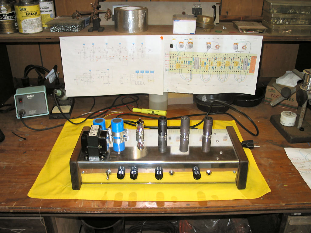
Here's an extra shot showing the typical messy multipurpose
workbench. Actually, this was a woodshop at one time. And if you look at these
pics closely you'll see evidence of plumbing, pool, air conditioning, sprinkler, and
electrical maintenance also.
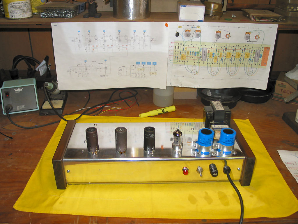
Rear view. But also, notice the schematic and layout stapled
to the shelf above the work surface. They're right in your face but not in the
way.
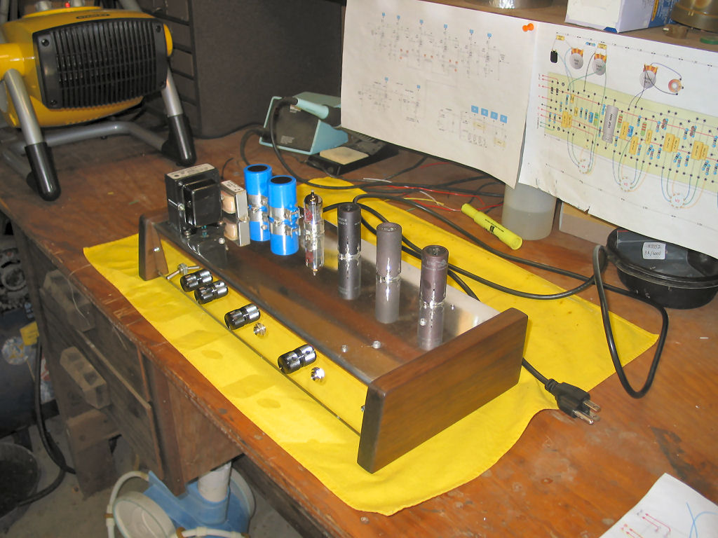
Side view. It actually got cold before I finished and I had
to buy a small heater. It doesn't heat the entire workshop, but it keeps the
workbench nice and toasty.
Download my original Visio schematic,
full size board layout, and drill guide
in a single PDF.
warbler.pdf (129KB)
(Note. This is the original circuit as
seen in the above photos. It's still here just for historical value. If you are
considering building this circuit, I highly recommend you look at the
Revision 2 circuit instead.)
Return to Index
|