|
February 18, 2013
The Warbler Revision 2, a
major overhaul
 What
began as a simple mod to provide a LED front panel indicator for the vibrato LFO
turned into a major overhaul. What
began as a simple mod to provide a LED front panel indicator for the vibrato LFO
turned into a major overhaul.
Here's a summary of the changes:
- The MIX control is a carryover from Revision 1. It
allows blending the wet signal with the dry signal.
- The TONE control was added to compensate for the
slight loss of treble through the modulator circuit.
- The FOOTSWITCH jack allows easy on/off function for
the vibrato effect.
- The BAL pot allows you to match the "dry" signal
level to the "wet" signal level at the inputs to the mix pot. I used a scope
to match the signals but you can easily set the BAL pot by ear. Just turn
the MIX to max CW and note the sound level. Now turn the MIX pot max CCW and
adjust the BAL pot until the dry sound level is the same. Repeat until
you're happy, then lock the pot.
- The LED flashes at the rate of the vibrato
oscillator. Although the LED also increases the LFO output signal, the
Warbler doesn't benefit from the increased signal. So, it's purely a visual
thang.
- V1 and V2 have been replaced with 5751s. The 5751s
sound good and are not prone to microphonic problems that I was experiencing
with the batch of milspec 6189s (12AU7) I had been using. I think the 5751s
may sound a little more crisp than the 6189s.
- V3 circuitry has been totally removed. It was not
needed.
- Power supply nodes E and F have been eliminated.
- V1A gain has been reduced to about 3.5. The overall
gain (input to output) is about 2.5. The reduced gain results in quieter
operation but still provides a nice clean boost that can be set with the
LEVEL pot.
- DC voltages and AC signal voltages have been added to
the schematic.
All these changes are documented in the revision 2 pdf
available at the bottom of this page. I don't anticipate any further changes.
And here are the updated pics, plus a short tour around
the bench...
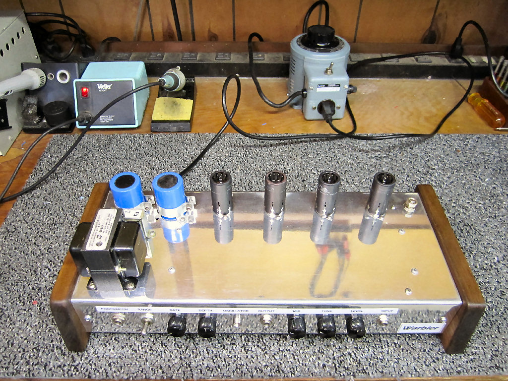
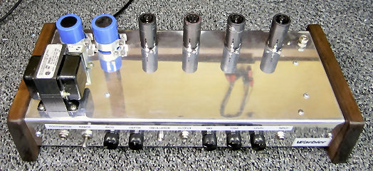
The control panel is busier now. Left to right... Footswitch
jack, range switch, rate, depth, oscillator LED indicator, output jack, mix,
tone, level, and input jack.
The balance pot was added just to the left of V1. It's
function is to match the "dry" signal level to the "wet" signal level at the
inputs to the mix pot.
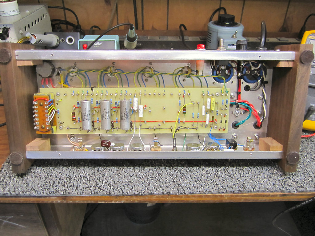
Not only has the control panel become busier, the board has
become less busy. A lot of components have been removed. Several values
have changed. And a few components have been added. The original 12.5" board
could now be shortened about 3".
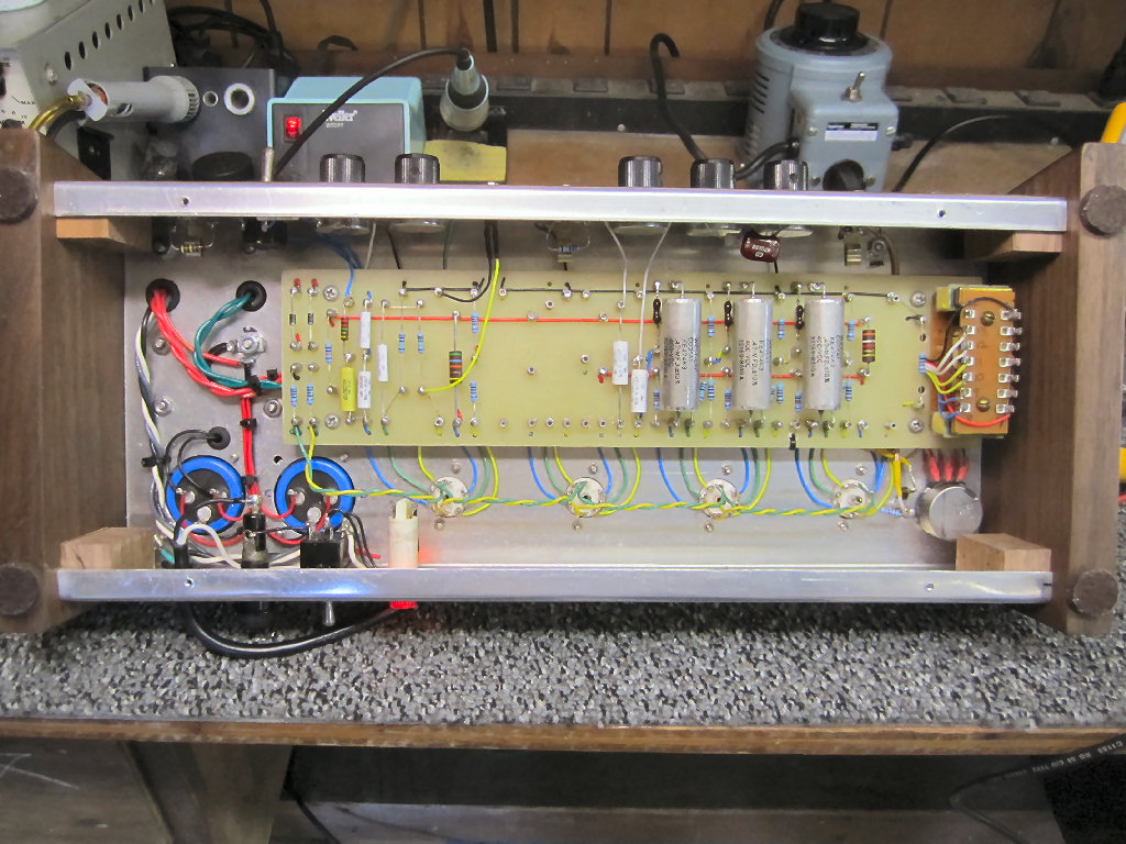
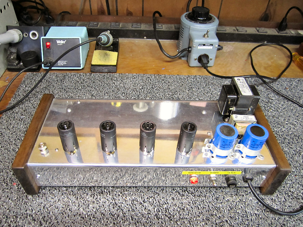
This view shows the chassis layout as seen in the board
layout drawing. I left the empty V3 socket in place rather than have to redo
the filament string. And who knows what revision 3 may bring!
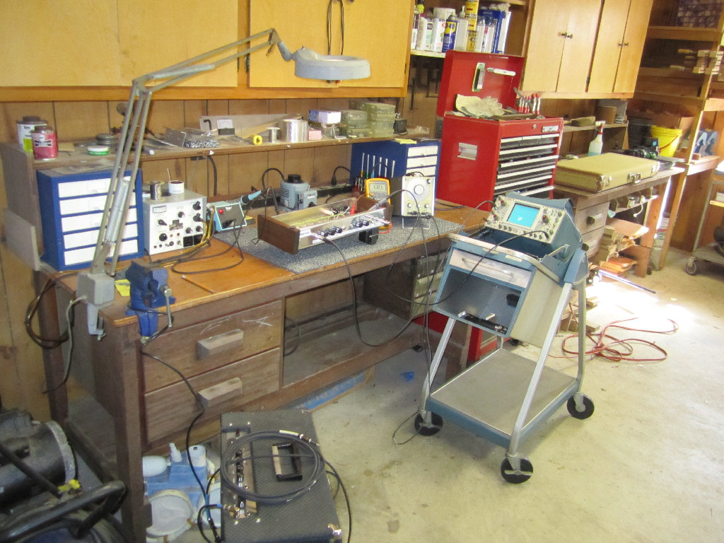
And here's the work area. Not too big, not too small.
Just right for my hobby interests. The workbench is still somewhat cluttered.
Maybe now that I'm retired I'll have time to organize better.
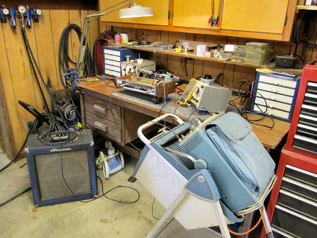
If you let your eyes wander you'll see that this bench is
used for much more than just electronic projects. BTW, that Ampeg ain't
what it seems to be.
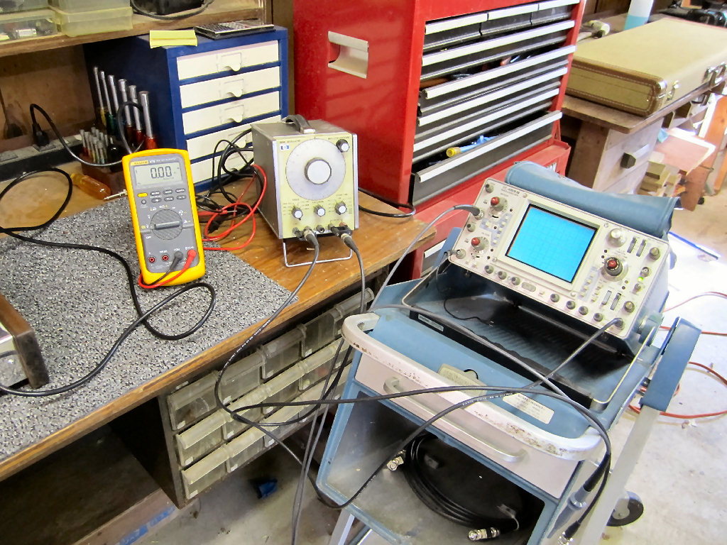
This is the test equipment that I used while building and
testing. These 3 pieces came from eBay. The scope cart was originally used for
the old Tektronix 545 tube scope.
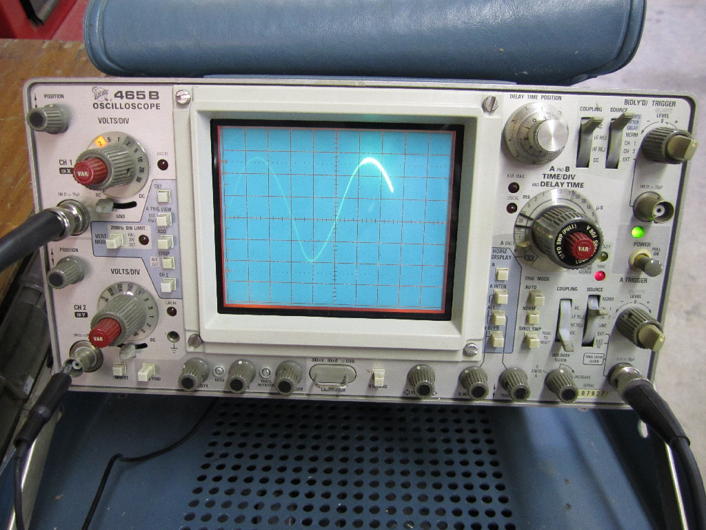
The scope is displaying the LFO sine wave. Notice that it's
not perfectly symmetrical.
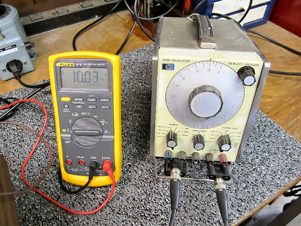
The Fluke 87 DMM is monitoring the vibrato LFO signal. It's
set to frequency mode and is displaying 10Hz. The HP 204D Oscillator is set to
provide a 200mV 1KHz sine wave signal to the Warbler input. It is also sending a
sync signal to the scope for external triggering. Triggering the scope
externally allows a stable display that is independent of the scope vertical
input. This setup allows the scope to display phase shifts as well as signal
levels as you step through the Warbler modulator circuits.
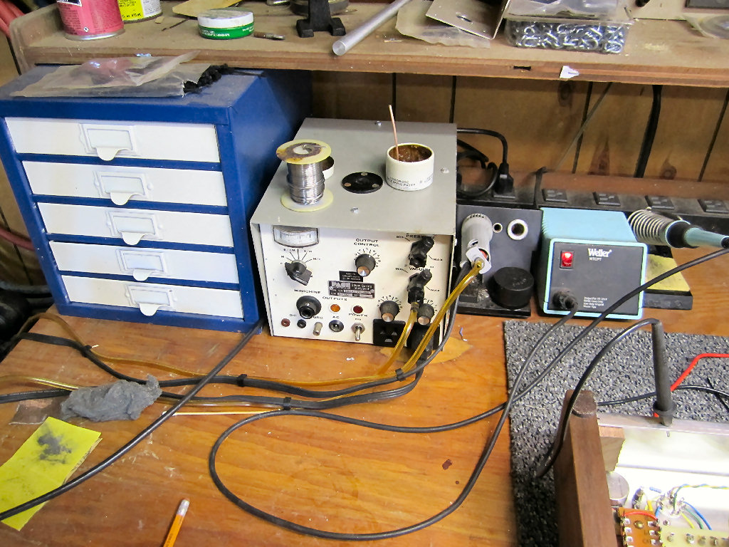
The Weller WTCPT soldering iron has been my choice since the
early '70s. And sitting just to the left is a Pace repair station. It has a
soldering iron, vacuum operated desoldering iron, thermal wire strippers, small
air compressor, and "Dremel-like" rotary tool. I mostly use it for desoldering
jobs.
Download the Revision 2 schematic and full size board layout in a single PDF
warbler_rev2.pdf
(181KB)
(Note. This revision contains
all the circuit changes mentioned above. This is the circuit I recommend building.)
Return to Index
|