|
January 12, 2006
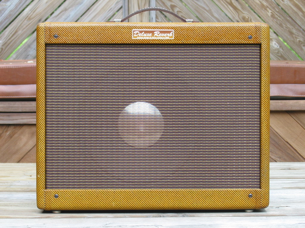
Tweed Deluxe Reverb? Never
heard of it! If Leo had wanted us to have one, he would have made it for us.
Who'd want it anyway?
........Well, I would! |
And I have for about 4 years now. It was 2002 and I had
just restored a 1957 Fender Harvard for an old high school buddy. Man, that amp
sure sounded good to my old ears. And I found myself drifting back to a chaotic
time in '65. I remembered how I would scoff at his little amp. Heck, he couldn't
even keep up with my old Silvertone twin 12! You know, the sixties was not as
focused on quality sound as "we" are today. There were no "boutique" amps.
IT WAS ALL ABOUT SOUND PRESSURE! CAN YOU FEEL IT! You old guys know what
I mean. I still remember the day our other guitar player showed up with a Super
Reverb. Now I couldn't be heard either! I took care of that soon enough though.
My first build back in '68 was a Sunn Sorado Bass amp. Sitting on top of twin CTS 15"
bass speakers with the biggest square magnets anyone had ever seen!
CAN YOU HEAR ME NOW!
Whoa. Got lost for a minute. Back to 2002. Yes, I kinda
liked that old Harvard. But it lacked a component that I considered essential.
THERE'S NO REVERB! Oh well, it is what it is. A long spring unit wouldn't even
fit anyway. And I wasn't about to suggest butchering that old piece of history.
And I didn't even know.....the seed was planted.
Then last November, I began itching to do one more build.
I hadn't done an amp since '76. Actually, I went acoustic and stayed that way
until 2003. I bought a Taylor 614CE and picked up an old Peavey Reno from eBay.
That sparked the old love for Strats. So, I'm checking out the 5E3 kits but it
just isn't exciting me to just assemble someone else's deal. Besides, that 5E3
is just too simple (from a technical standpoint). But in my quest to calm the
itch, I realized that the Tweed Deluxe cab was 20" wide. Hmmm, where's my tape
measure. I think a long spring may fit. And so, the seed sprouted. I barely remember Christmas. But I didn't care. I
was alive and 20 years old again and excited and running around gathering up
parts and asking questions. What a joy for an old fart to
rekindle a boyhood passion!
.....And so I was off to build my own Tweed Deluxe
Reverb.
| In
the beginning... The project took life by
first taking the Deluxe Reverb AB763 schematic and stripping out the normal
channel and tremolo circuits. Then I added a bright switch and middle
control. After some fine tuning in Visio, I cranked out my final
working schematic.
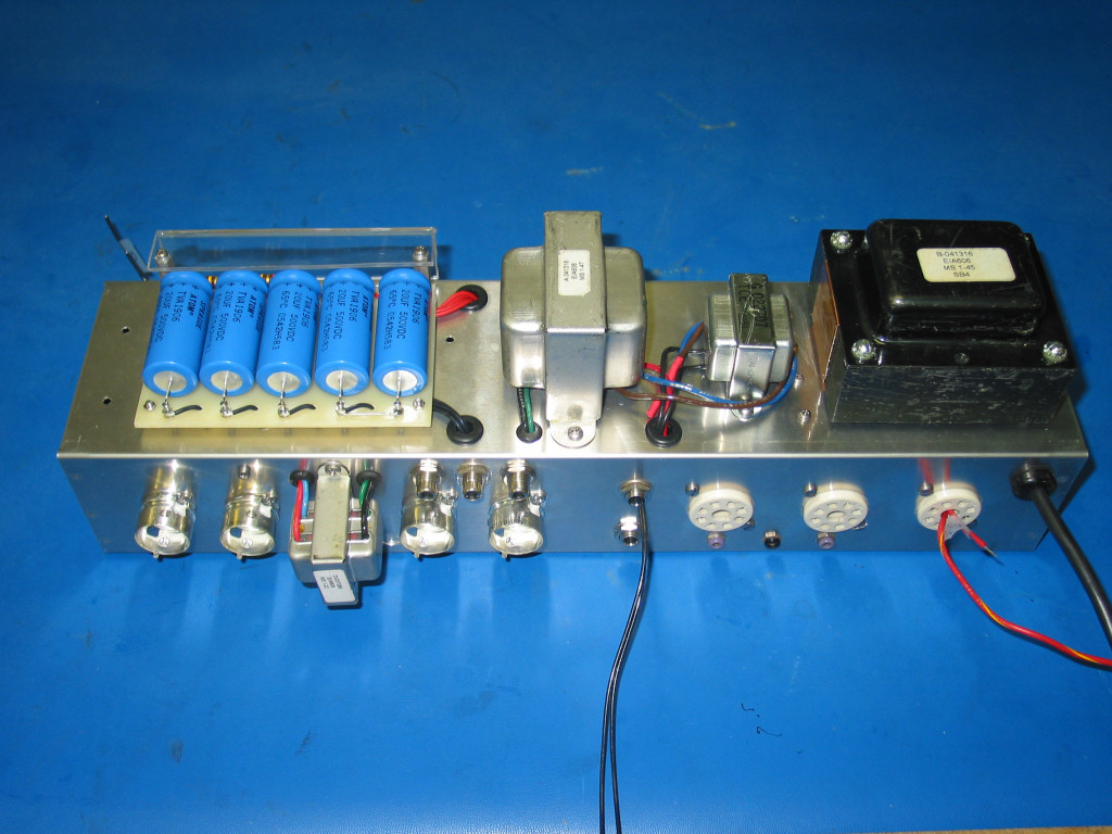
The aluminum chassis is a Hammond 1444-20, 17x4x3.
It's really thinner than I like. If I were to do this again, I'd use the
steel version of this chassis. It's not that much harder to work with.
However, it would have been a special order from Mouser, so I opted for
aluminum.
The PT cutout was done with a jig saw and some hand
filing. A router guide template would prove useful if doing several of
these, but I had a nice hole cut faster than I could have built the
template. All other holes were done in a drill press using HSS bits or a
step bit. The octal socket holes were punched with a 1 1/8" chassis punch.
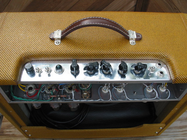
The control panel layout was done using Visio. The
Tweed Deluxe cabinet has a 2" x 12 1/8" cutout, so I had to do some careful
layout work to get it all to fit correctly. Layout from left to right is
fuse, power, standby, indicator, reverb, master, bass, treble, volume,
bright, inputs. That's BUSY!
I had one design layout flaw that I caught while
wiring the filament string. I had placed the reverb in/out/footswitch jacks
below the reverb transformer for a nice looking and easy wiring job. But my
filament string was gonna be tucked away under the bottom lip of the chassis
and would pass very close to these jacks. So, to minimize hum, I relocated
the jacks and put a small cover plate over the original holes.
All caps came from Mouser. Materials to build the
turret board came from Hoffman. The safety shield for the caps was cut from
a sheet of 1/8" acrylic that was sandwiched between two wood blocks in a
vise. A heat gun was used to make the bend. Hopefully this will keep
careless fingers off the business end of those caps!
The transformer set is from a '65 DRRI and was
provided by MikeyMann. All wiring (except power cord and transformer leads)
is either 18 or 22 gauge teflon insulated 19 strand silver plated copper. I
had some on hand and bought the rest on eBay. (There really isn't anything
that can't be had from eBay!)
I already had all the miscellaneous stuff, tube
sockets, switches, indicator, fuse holder, standoff turrets, etc., from my
last build in 1976. Those gold plated sockets looked brand new. Some of the
other stuff got a good cleaning.
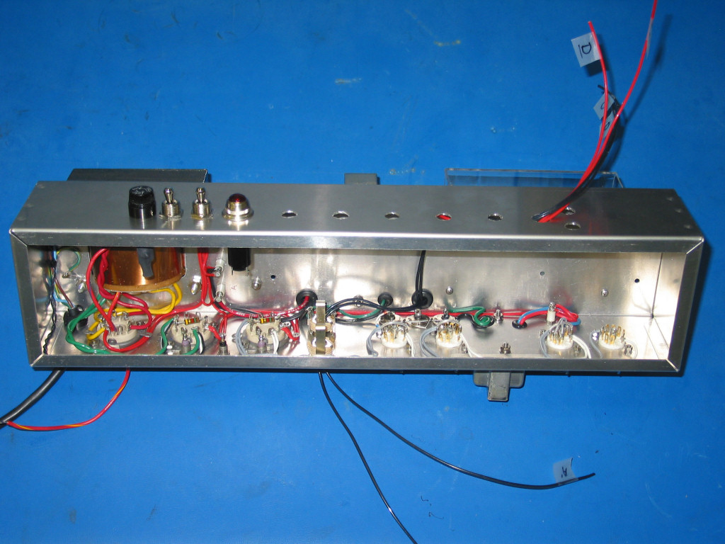
The next phase of this project is going to get
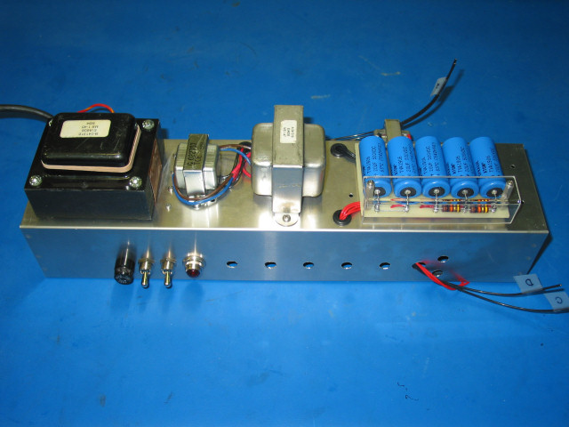
crowded, so this is a good time for some preliminary checks.
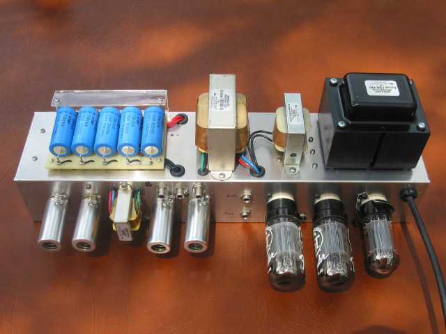
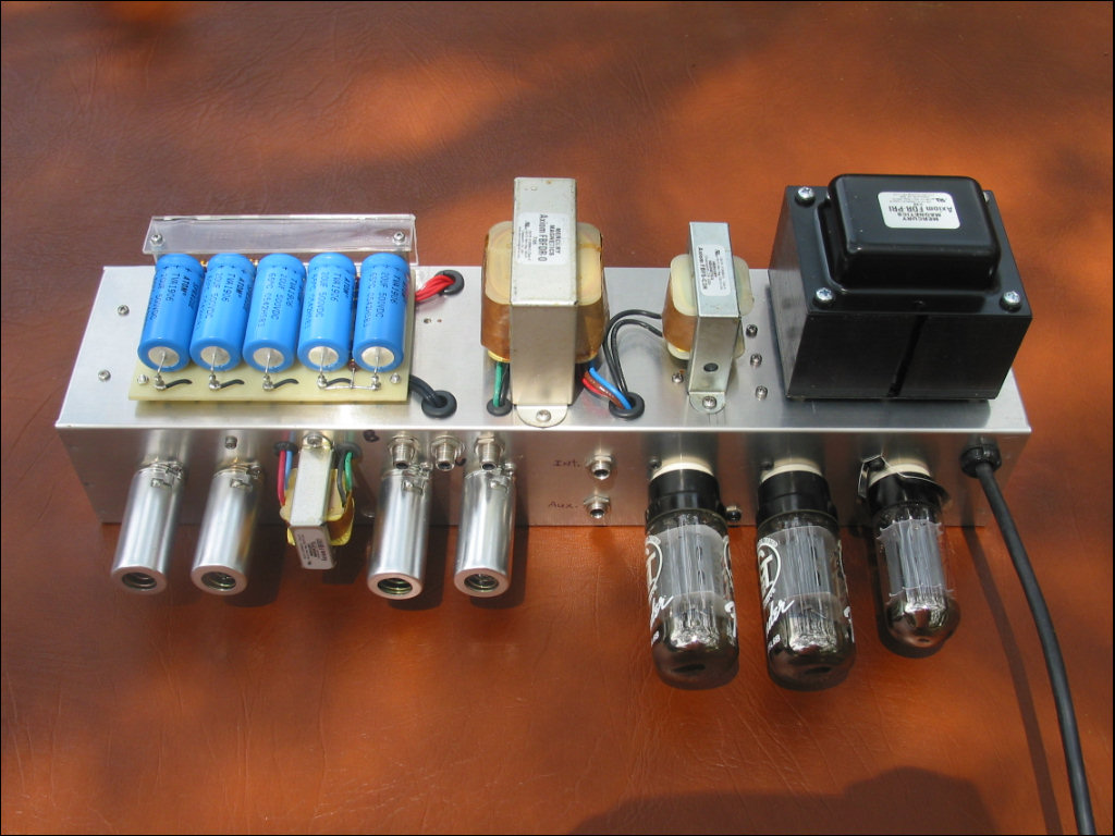
All external components have been installed but not
necessarily connected. Note that the HV center tap (red/yellow) and
bias tap (red/blue) are not connected at this time. At this point I did a
first power on check to verify PT operation and rectifier and filament
string wiring. All was well so I put all tubes in for a quick check for
lights. And finally, a voltage check between rectifier cathode and HV center
tap showed the expected unfiltered 120 hz. DC voltage. All checks
at this point passed so it's time to move on. |

 |
| The
tough stuff... Building the main board was
actually several challenges rolled into one. Divide and conquer. The board
needed to be about 2" wide to provide adequate wiring space inside the 4"
wide chassis. I spent several hours working with Visio to generate my layout
template. Then several more hours were spent going over and over, refining
and verifying that everything was correct. It's the old carpenter's rule,
measure twice, cut once. I didn't want to find out later that I needed one
more turret lug, or a jumper here, etc.
The final template measured 2.2"x10.8". Now the fun
part. The G10 board was cut to size and the full size template was printed
and attached to the board with double sided carpet tape. All holes were
carefully center punched and then drilled at the drill press. (This method
works fine for a one of a kind board) Then I used Hoffman's little flaring
tool set in the drill press to install the turrets.
Back to the soldering station to install jumpers,
wires and load the components. BTW, all resistors are carbon comp, 5%
tolerance, high reliability (yellow band = 25ppm, whatever that means!) mil
spec.
Here's the
board layout if you're curious. |
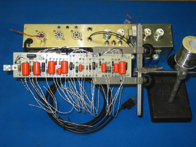
The board is fully loaded and ready to be installed.
Actually, this was to be the most challenging part of the entire project. I really
could have used a swivel jointed curved needle nose pliers with a
retractable cutter on the tip. (and one more quart of nerves!) By the time I
finished the tube side wiring, I was exhausted. The control panel would have
to wait. And there ain't gonna be no rematch, so
don't ask. |
|
Ground is ground. Right??? Now that's a science all
by itself! Not just with amp building, but with any complicated electronic
system. I work for FAA at an enroute radar station and believe me when I say
that a lot of R&D goes into a grounding and bonding system at such a
facility.
So I read up on amp grounding schemes. Aiken has some
excellent reading. And I pondered what to do....Star, multi-point star,
buss. They all have good points and grounding does not need to be taken
lightly, especially with an aluminum chassis. My ground system was the very
last thing I wired. I was hoping to come upon some magic solution.
But in the end, I went with my tried and true method
from 30 years ago. Single Point Ground is what I called it back then. I
guess some would call it a Star today, but hey, it could even be a 2" long
buss! |
 |
|
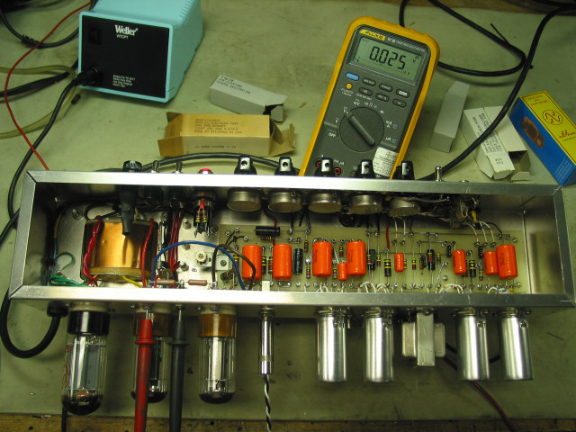
Something's burning... The chassis is 90%
complete at this point. I say 90% because you can never quite be sure that
some gremlin is not gonna rise up and piss in your coffee during the first
burn. I got lucky. The components held up and I only had one minor
wiring error. The coax cables that feed the grids for V1 run underneath the
main board. Yep, they got reversed. An easy fix that I caught just prior to
first burn. I dummy loaded the output and set the bias for 25 ma idle
current. All plate, screen, grid, and cathode voltages were checked and
found to be acceptable. I just let it cook that way for the remainder of the
day. I think it's always good to just let the juices flow at idle for a
while before applying an input signal. I made a point to stop, look, listen,
and smell every few minutes during the first hour. By the end of the day
confidence was high.
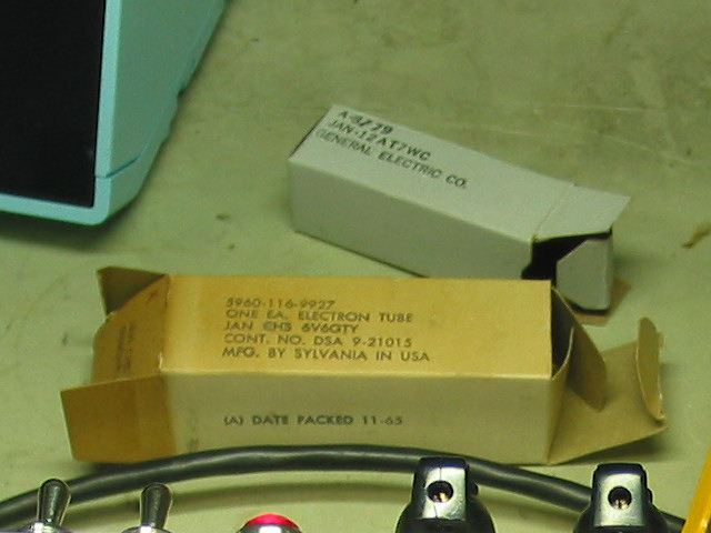
BTW, take a close look at that
old brown tube box just north of the chassis. Catch the packing date on that
dude? That's the same year I got started in all this stuff! |
First burn is always a rush. It's
usually either Miller Time or a very humbling experience. |
| It
feels like the first time... Well, it's
Friday morning, I'm home alone, what shall I do?
I think I'll try to make some noise. I connected into
one of the TRRI speakers, strung out the reverb cables and turned it on. It
made some noise all right. SQUEALED LIKE A STUCK PIG! Power off immediately
and fire up the soldering iron. My bet is the OT plate connections are
reversed. Hey, it's a 50/50 thing and I got it wrong the first time.
The Strat is plugged in and I'm having fun. Something
is not quite right though. Sounds like the gain is turned way way up even at a
minimal setting. This one took a couple hours to find, mainly because I had
to strongly suspect a wiring error or bad component. I danced all around the
problem for some time before realizing that the error lay with my rendition
of the original AB763 schematic. The vibrato channel has an extra gain stage
due to the loading effect of the reverb and tremolo circuit. The tremolo pot
puts a 50K resistance on the signal path just prior to the mixing resistors
that feed the PI. I had totally omitted this resistor! Gator clipped a
resistor in and everything quieted down. The final fix is
a 100K pot for a master volume control. I'll just give up the 'Middle' tone
control. |
After debugging, I spent 4 hours with my strat tied to
this thing! I couldn't leave. It felt good. It sounded good. By the time I
realized I needed to move on, I'd celebrated too much to do any more work.
The cab work could wait 'til tomorrow. Anyway, I just thought of another tune
to try! |
|
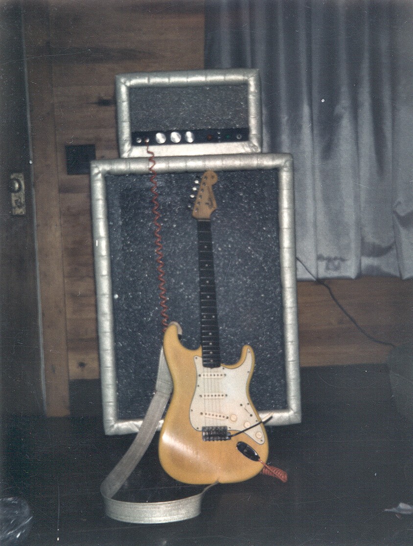
Almost heaven... It's tomorrow! Imagine my
joy when this chassis slipped snuggly between the side cleats in this cab!
Actually, this point was my biggest research
challenge. I posted the question "what is the exact distance between cleats"
in several different places.... Mission Amps, Mo Jo, Weber, and on AGA. I
got a variety of responses, but no one could give me a measurment. Well,
actually, one guy on AGA nailed my question with real numbers, but by this
time, I had charged ahead and bought the cab from Marsh Amps on eBay. I'm
pretty sure he's sourcing from Mo Jo. I knew it would be within 1/2'
and was prepared to modify the cleats to make my chassis fit. I was
pleasantly surprised.
There are only a few things left to do now, 1) Shellac
the cab, 2) make a faceplate, and 3) get a speaker.
Shellac is done. I applied 4 coats of Zinsser's Amber
cut 50/50 with denatured alcohol.
As
it turns out, the speaker selection is going to be limited. There's not much
room in that cab. I'll either have to stay with the one I borrowed from the TRRI or find a suitable low profile model. |
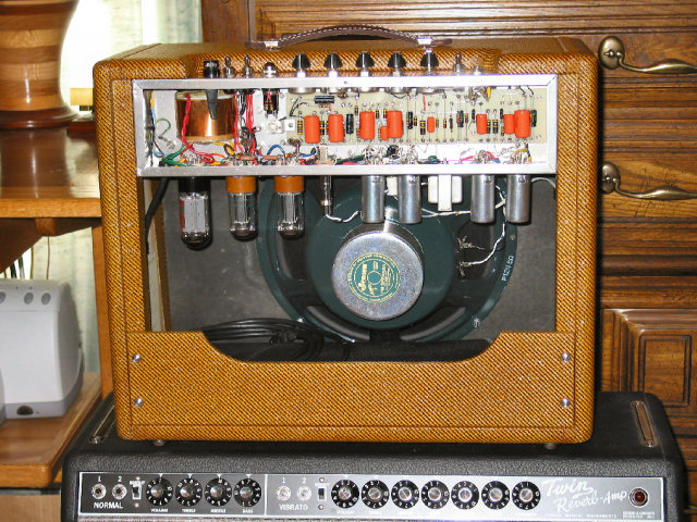
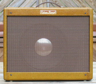
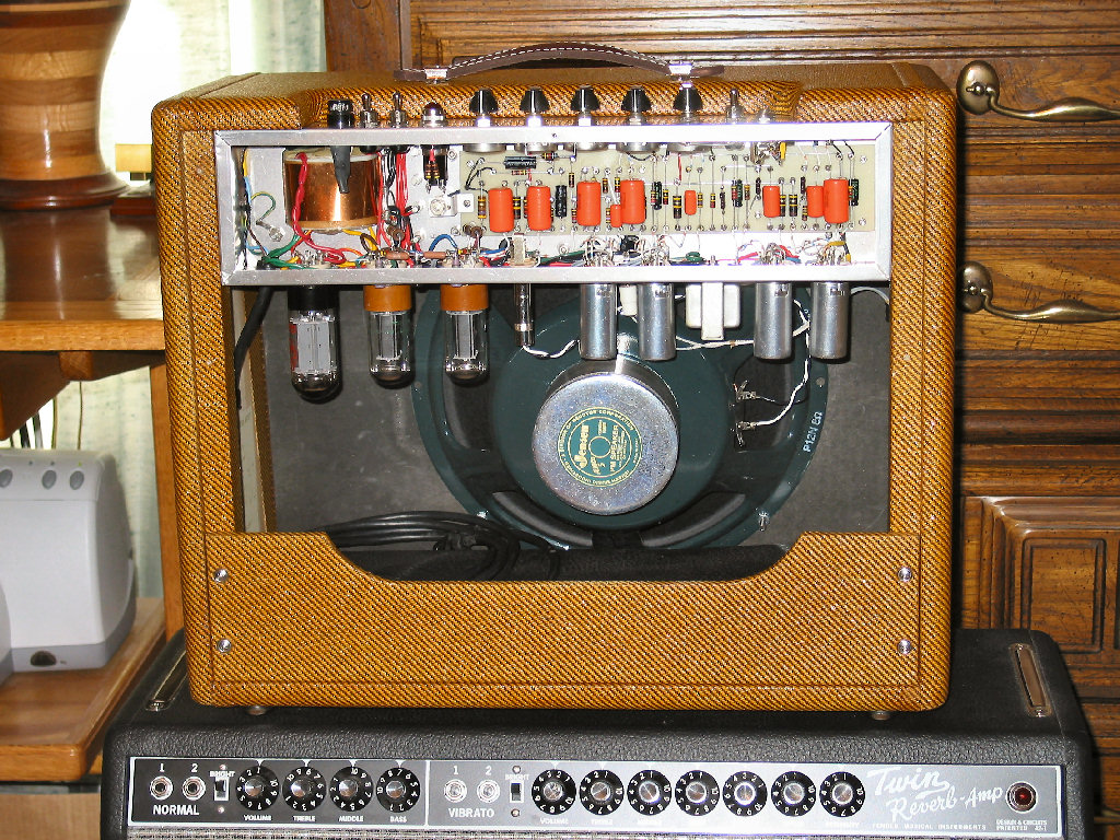
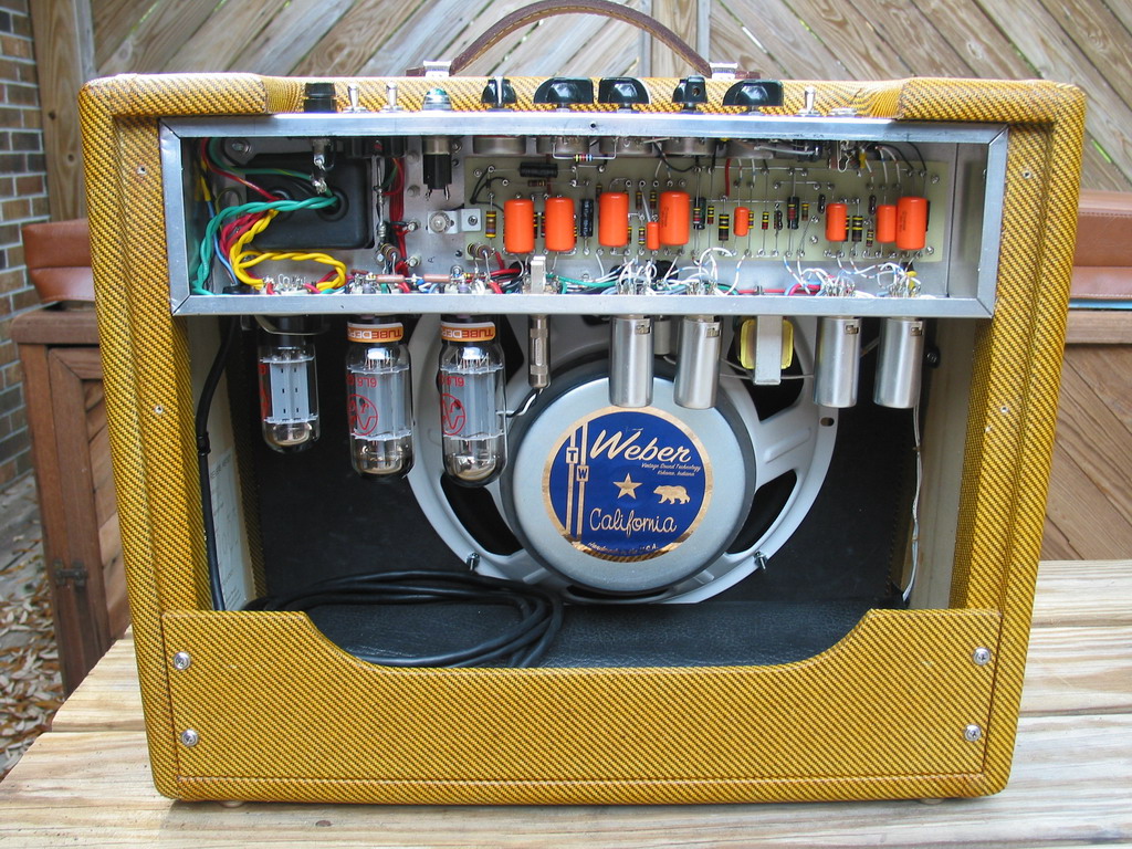
Almost done. It's been a challenge to fit everything from
the onset. As you can see, putting it all in the box was no exception. But
my friends, you're looking at the genuine original, one of a kind, AB763
Tweed Deluxe Reverb. Who
cares? Probably no one. And certainly not me. Hey, I got one! What a trip!
As you can see, the speaker selection is done. I chose
the Jensen P12N reissue. It has a much brighter sound than the borrowed
C12-K from my TRRI. |
I guess a home brew is never quite completed and I doubt
this will be any different. I still have a couple ideas to try while the adrenalin is
flowing. And I may upgrade the iron. But this was never a quest for the ultimate
amp. It ain't the arrivin' but the gittin' there that turns my crank. And I sure
had one sweet ride!
Thanks for listening....Steve Luckey (aka 57chevy) . . . . January 21, 2006
Update (April 22, 2006)...
Well, I guess you knew I couldn't let it be. And I knew
it too! I really enjoy playing through this amp, but I love tinkering under
the hood.
So I made some major changes. All the iron has been
upgraded to Mercury Magnetics and I've switched to 6L6s for the output. I'm
currently running on borrowed Groove Tubes from my TRRI but will be changing
to JJ Teslas before the end of the week. With the bias set for 46 milliamps
and the plates at 394 volts, the static plate dissipation is 18 watts. This
amp truly is a prime example of a wolf in sheep's clothing!
The sound is fuller on the bottom and the sparkle is
still there on the high end. I don't think I'll be switching back to the
6V6s anytime soon.
While I was under the hood, I removed the
Pentode/Triode switch. That was a nice toy to play with, but after a month I
found I was just leaving it in the Pentode position. An external speaker
jack now occupies the vacated switch hole.
I'm still waiting for a faceplate. A local trophy shop
says they can do it but with spring sports season in full swing, they're too
busy for now. Meanwhile, I've used Visio again to create and print my own.
It looks OK printed on photo paper but is not very durable.
(June 28, 2006)...
The 6L6 JJs have been running fine for over a month
now. I finally dropped the idea of a faceplate. I polished the front panel
to a 'near' mirror finish and used white dry transfer lettering. Looks good!
Oh, and I've replaced the Jensen P12N with a Weber
ceramic California.
The 'Tweed Deluxe
Reverb' is done!
I hope I get as much enjoyment from playing this amp
as I did from building it.
Epilog (July 1, 2006)...
I had so many extra parts left over from this project
(transformers, speaker, tubes, etc.) that it seemed a shame to just stick'em in a
box. But that's exactly what I did....sorta!
Take a look ...
Lil Sister
|

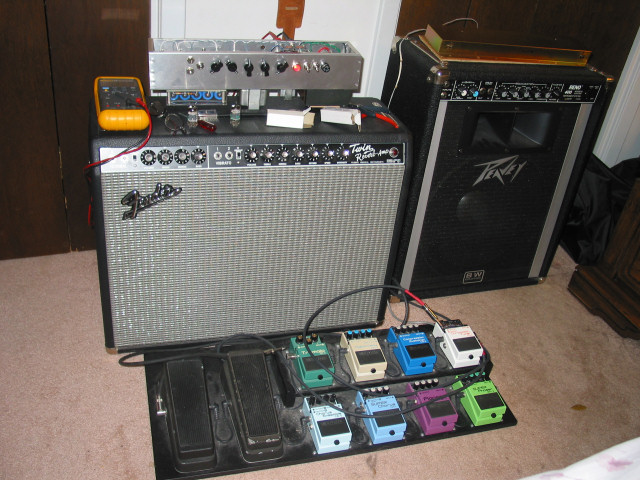
The wolf in sheep's clothing! Still looks innocent enough. The
Weber shines through.

Popping the hood reveals the super charged drive
train.... All Mercury Magnetics iron driving JJ 6L6s which in turn drive a
Weber California!
Tight control panel.
The wolf! MMs and JJs pump out 28-30 watts of unclipped
power into the new Weber Cali.
Still an AB-763, although I now hesitate to call it a
Deluxe Reverb.
|
Download the
schematic and board layout
Return to Index
|


