|
July 27, 2017
Supro S-6424
 I
finally got around to building a Supro amp. I recently heard a demo of the new
Supro 1624T Dual Tone amp and was impressed so I started gathering info. I took
a look at the original 1624T schematic and realized there was only one
tone knob. So why was Supro calling it's new 1624 a "Dual Tone"? It didn't take
much longer to realize that the new 1624 had some major differences with the
original 1624. Things like an extra 12AX7, two tone controls, and linkable
channels (probably where the "Dual Tone" name came from) made it obvious that
this new amp was not a reissue clone of the original 1624T. But I was intrigued
by the 6973 power tubes and also hooked on that demo, so here I go again.
Besides, everyone wants to sound like Jimmy, right? I
finally got around to building a Supro amp. I recently heard a demo of the new
Supro 1624T Dual Tone amp and was impressed so I started gathering info. I took
a look at the original 1624T schematic and realized there was only one
tone knob. So why was Supro calling it's new 1624 a "Dual Tone"? It didn't take
much longer to realize that the new 1624 had some major differences with the
original 1624. Things like an extra 12AX7, two tone controls, and linkable
channels (probably where the "Dual Tone" name came from) made it obvious that
this new amp was not a reissue clone of the original 1624T. But I was intrigued
by the 6973 power tubes and also hooked on that demo, so here I go again.
Besides, everyone wants to sound like Jimmy, right?
After more research I found that the S-6424 was identical to
the 1624T except that it did have two tone controls. One more knob is a good
thing, right? So I set about designing a board layout for the S-6424. I used the
same ole Fender/Marshall design, tubes across the back, knobs on the front, and
board down the middle. This layout has served me well for all my builds and
should work well for this Supro too.
I used a Hammond AO-43 amp as the donor for the Supro. As
it turns out, the power transformer and output transformer are a very good match
for this circuit. Voltages are very close to the original and the OT impedance
ratio (7128Ω:8Ω) works very well with the 6973 tubes. I followed the schematic
exactly except for the inputs. I used a single input jack with a three position
toggle switch to select either channel or both channels. And I used a 1M switch
pot for the Intensity control because I could not find a 500K (works just fine).
I also replaced the 250Ω cathode resistor on the output tubes with a 470Ω to
lower the idle dissipation to 18 watts.
It's a success. This amp turned out pretty good. I'm
calling it done. I've played the amp through several different speakers,
Celestion, Weber, Jensen. My favorite is the Jensen P12N alnico. Still don't sound like Jimmy
(haha). Maybe I need a Tele! The only
thing I would do differently is wait until winter time to build it. July in
Mobile is not a good time to do this stuff without airconditioning. Here are a few pics...
First a little chassis work...
I chose a 17.5 x 6.5 x 2.5 chassis (mainly because I had one on hand) but this
amp could easily fit a 12.5 x 6.5 x 2.5 chassis.
Drilling for noval sockets and larger holes such as pots, fuse, etc. was done
with a small Greenlee step bit. Holes smaller than 1/4" were done with standard
HS drill bits. Tube socket holes were tapped for 4-40 or 6-32 screws. I used a
Greenlee radio chassis punch for the octal socket. Transformer cutout was done with
hand drill, jig saw, Dremel, assorted files, and lot's of elbow grease!
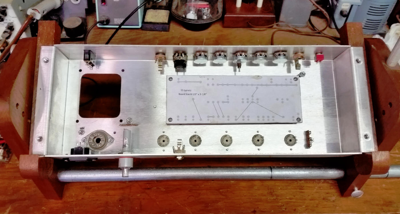
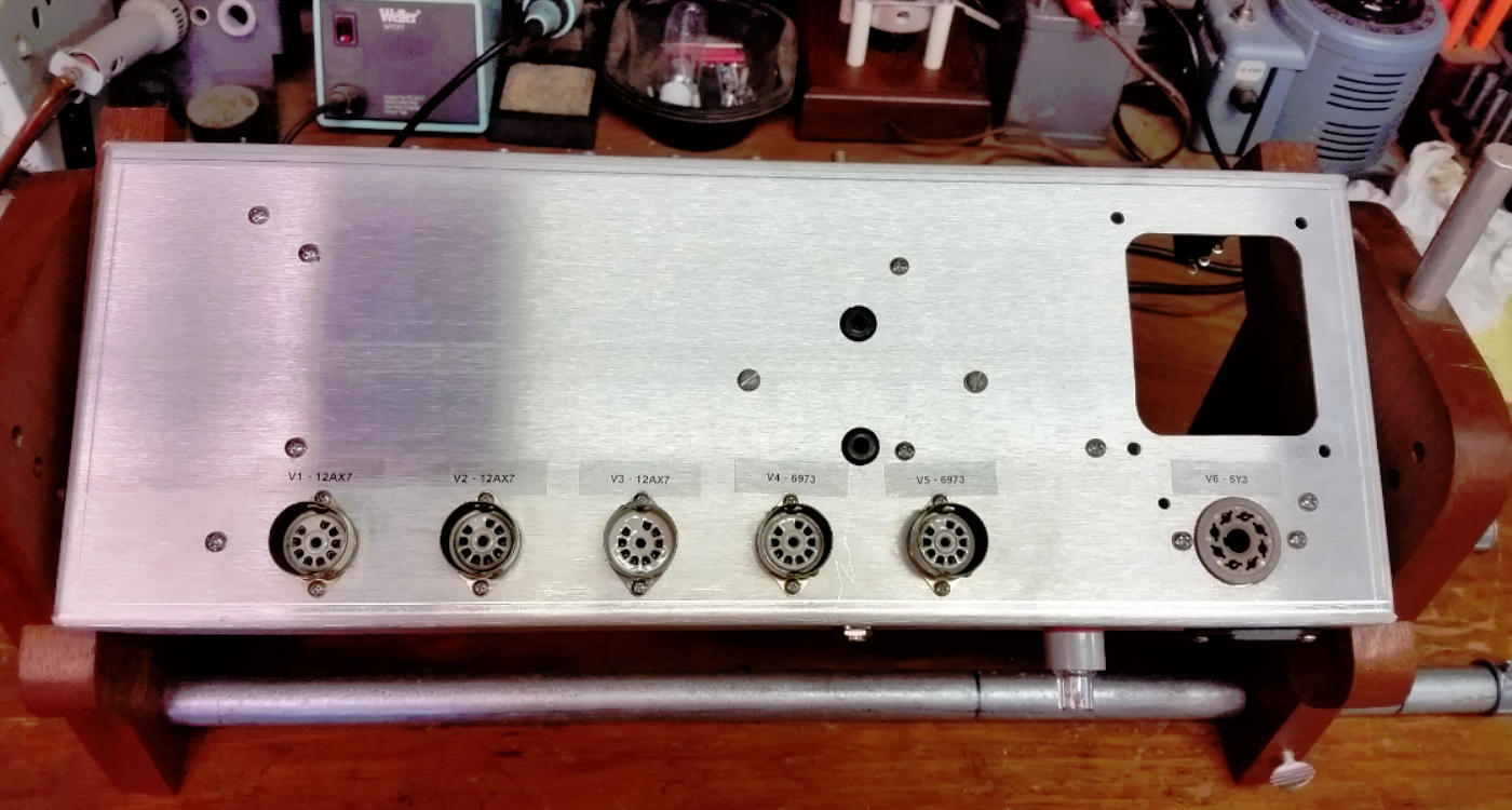
Chassis work is done and all components are dry fitted. Lot's of room in this
chassis.
Now to build the board...
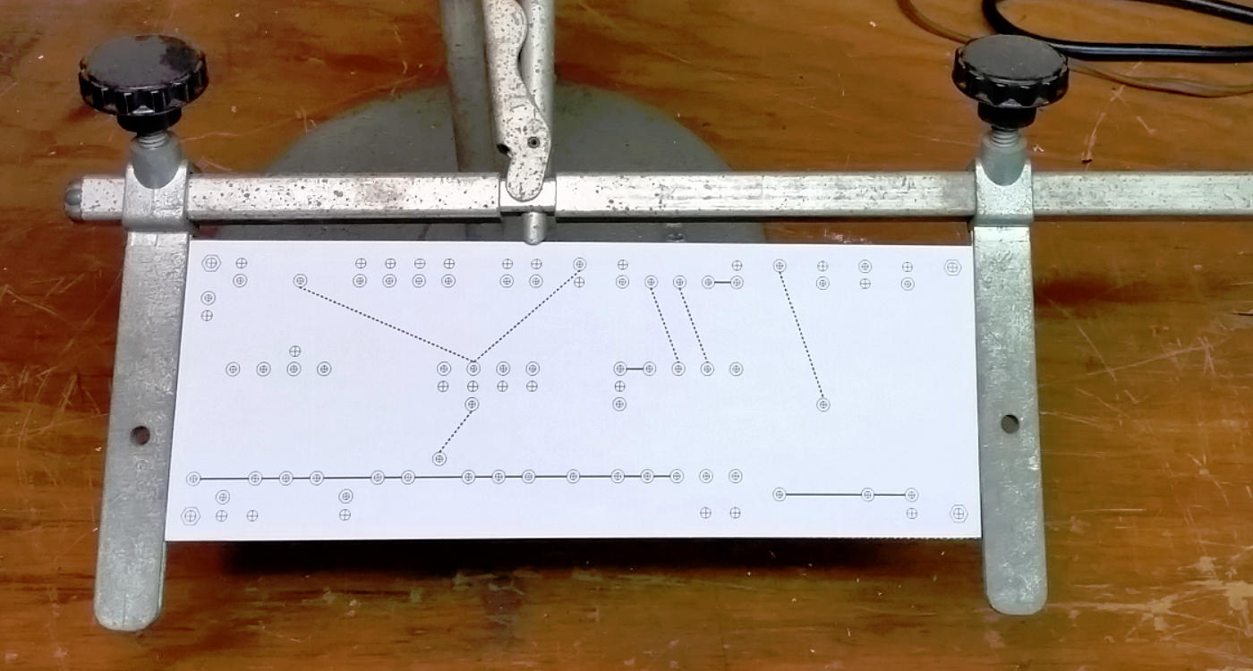
I apply the full size drill guide to the board using double sided tape. I'm
considering using a spray adhesive for future builds.
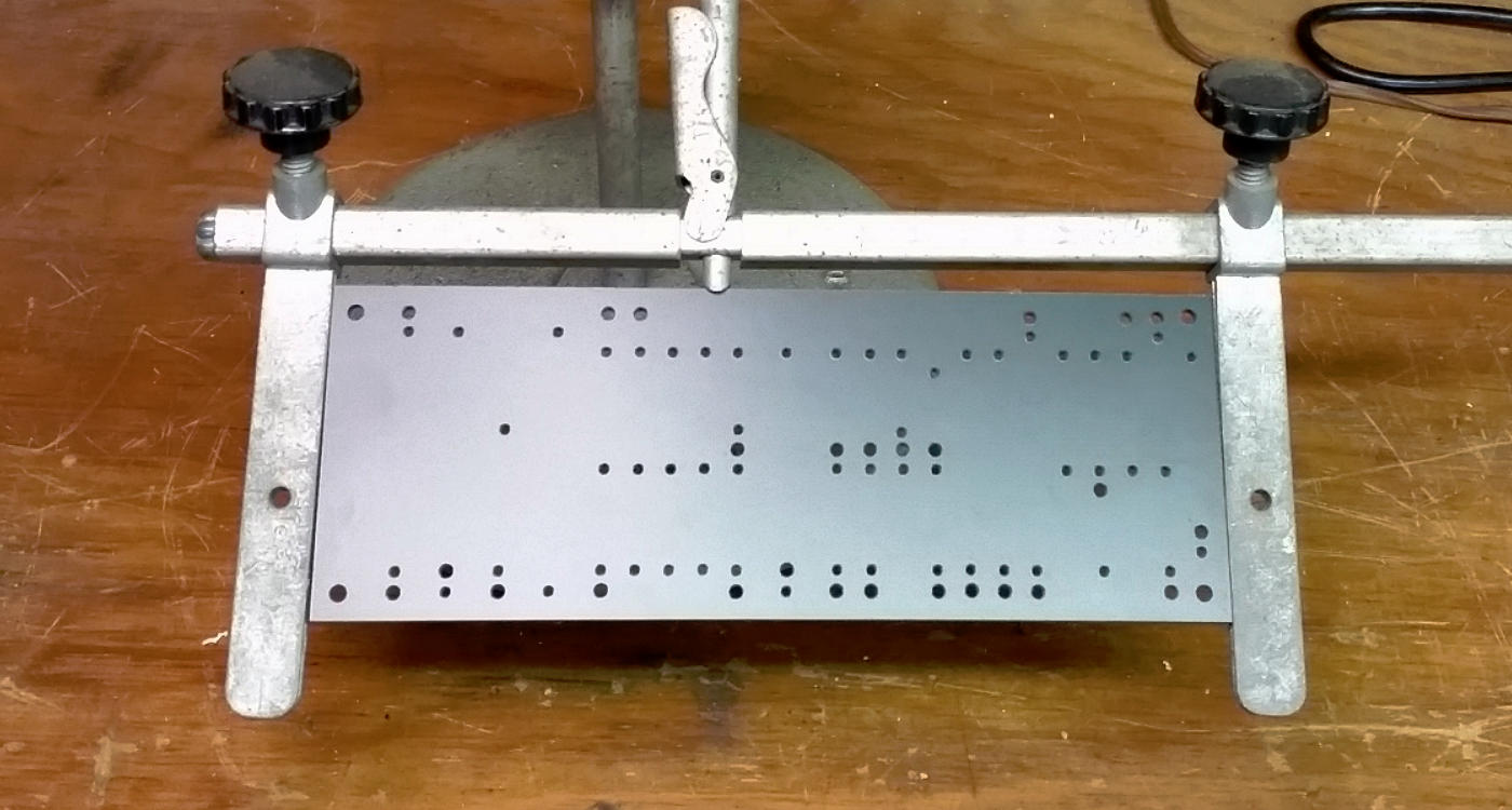
Board is drilled at the drill press.
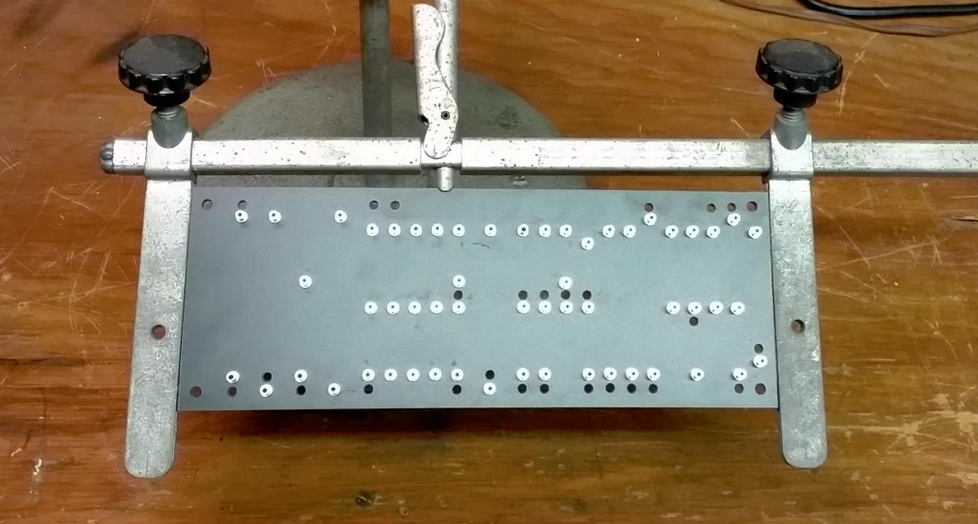
Turrets are swaged at the drill press using Hoffman's turret tool.
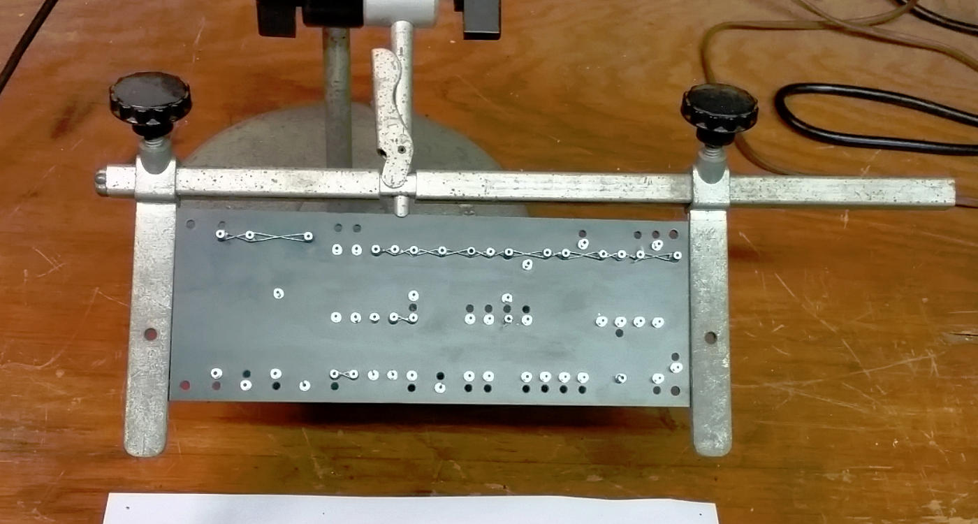
Board is laced and under board jumpers installed.
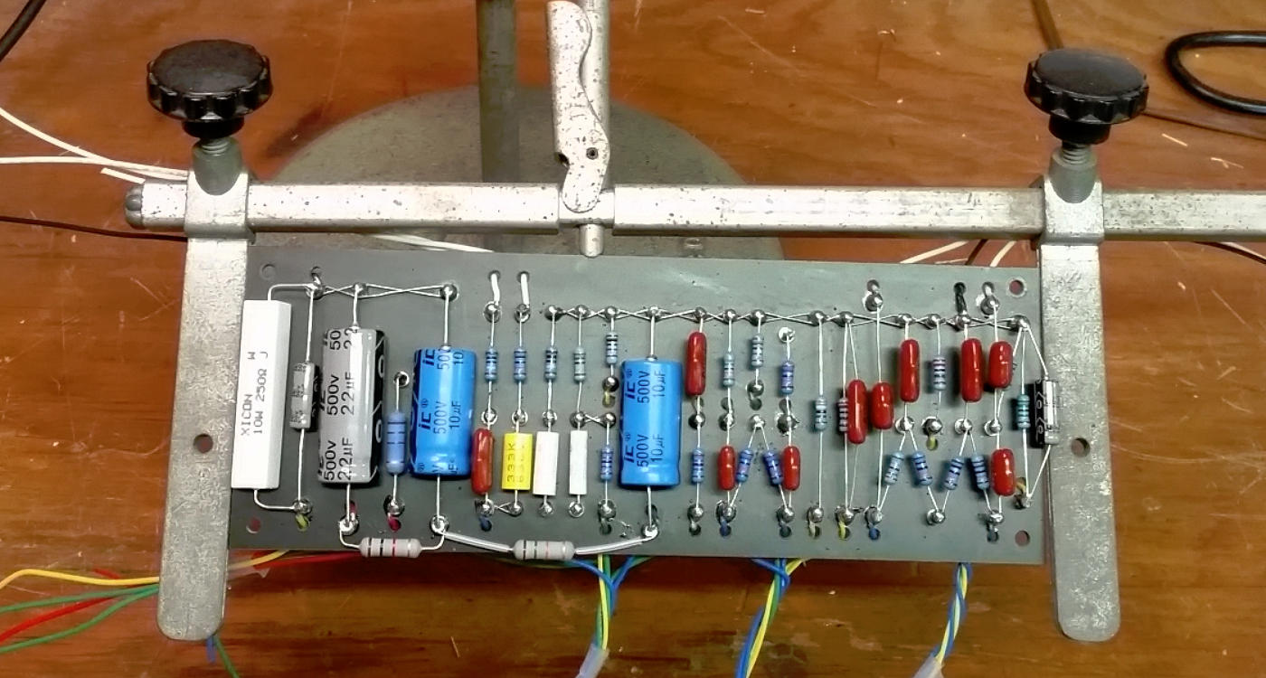
Components and wires loaded. Board is ready to be installed
in the chassis.
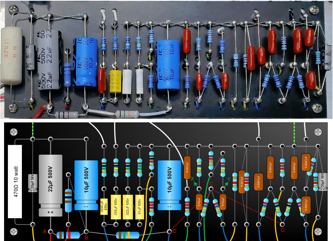
Comparing the finished board and Visio layout. Using my full size custom component shapes
makes it easy to create a full size board layout that will closely match the
finished board.
No guessing if your actual components will fit. WYSIWYG!
Finally, wiring the chassis...
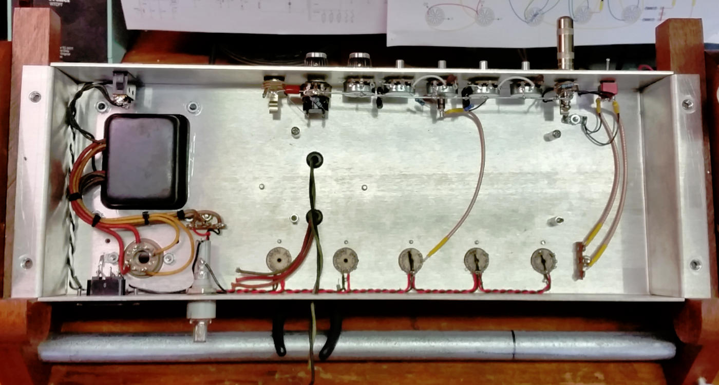
Filaments are strung and tested using a bench filament transformer. This is the
least enjoyable part of the whole project. Just grin and bear it!
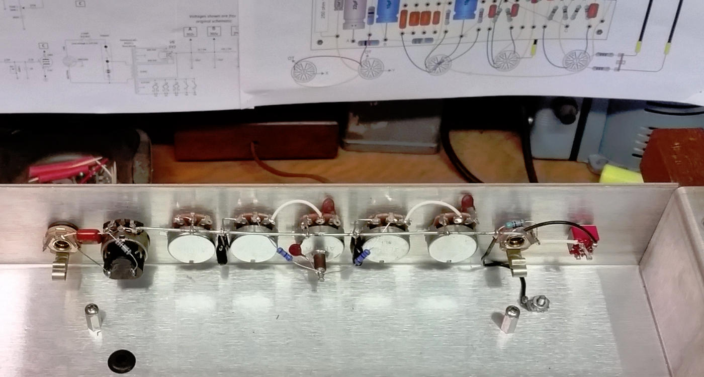
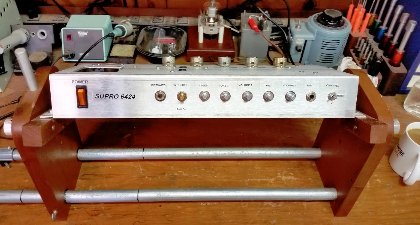
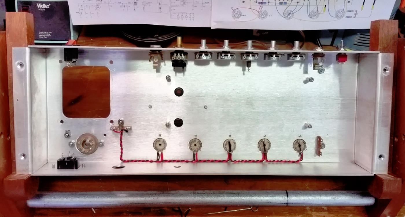
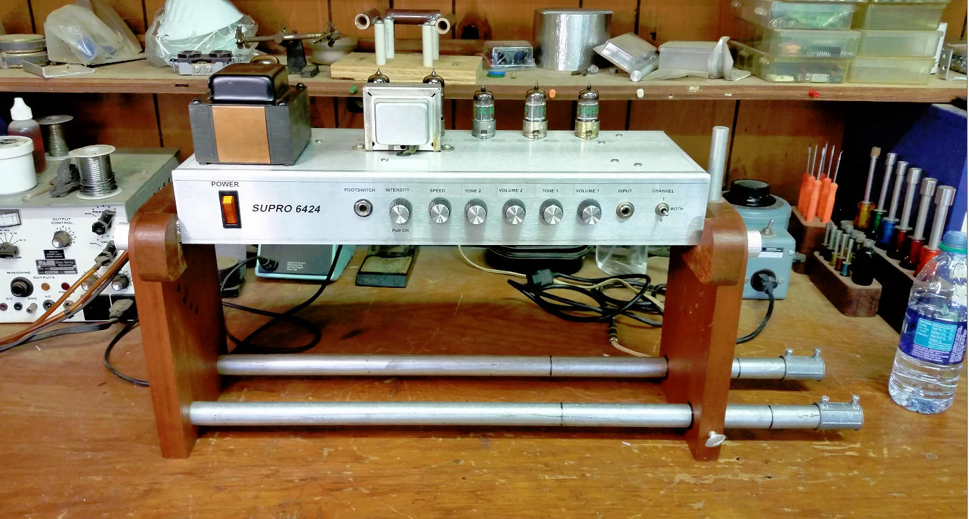
Control panel is wired. Notice the standoff turret soldered to the back of a
pot?
Shielded cable added and PT wiring is complete. This is the point where I do the
first power check. Plug in tubes and make sure they light up and check voltages
on the rectifier tube. All OK.
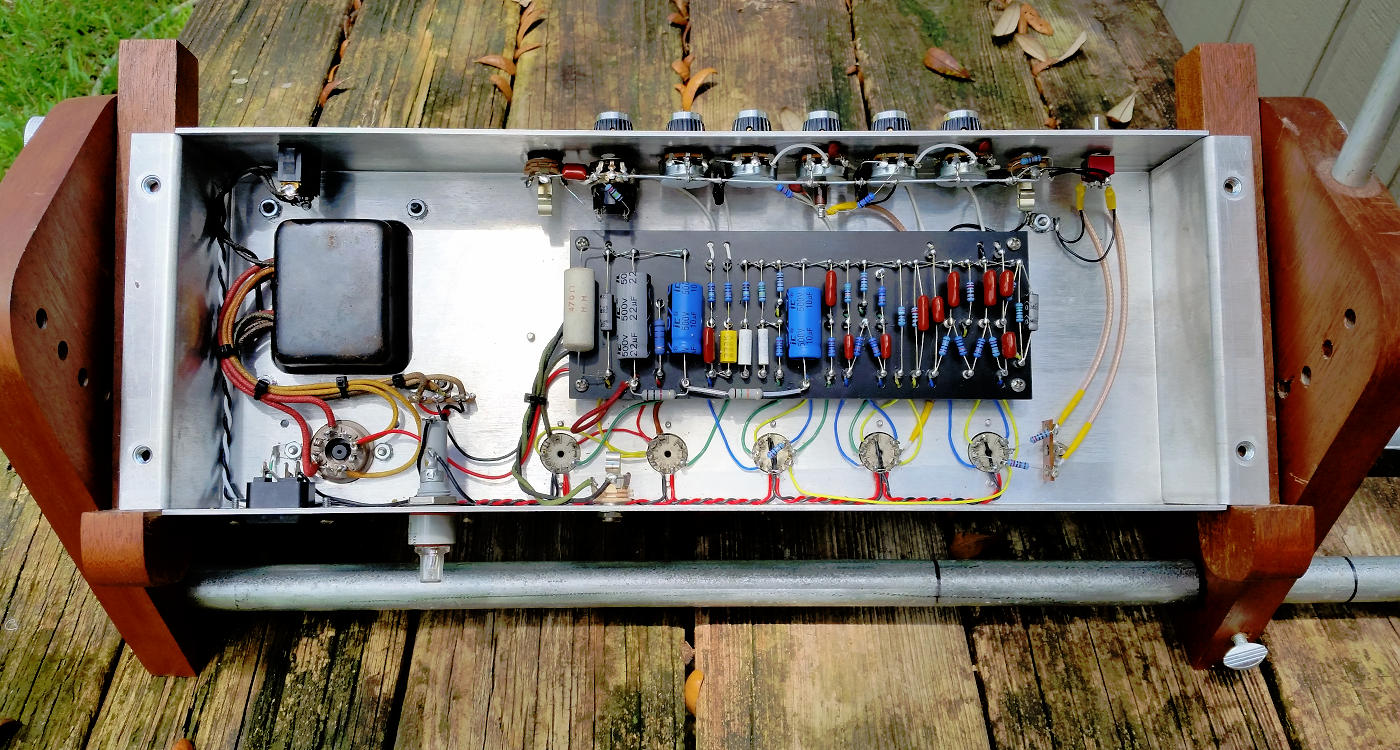
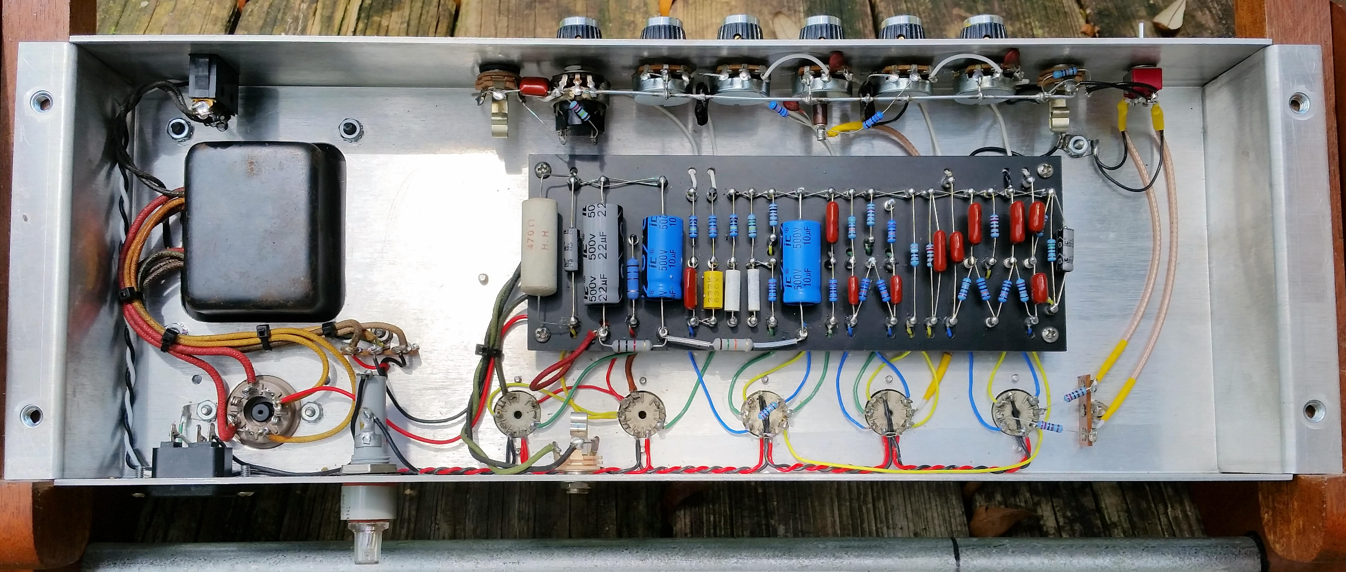
Wiring is complete. Voltage checks are done and guitar plugged in. Everything
looks and sounds good. Tremolo works fine. The power tubes were idling at 25
watts! I replaced the 250Ω cathode resistor with a 470Ω to drop the idle down to
18 watts. (click pic for high resolution pic)
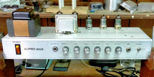
A few more pics of the completed amp. No cab for this project.
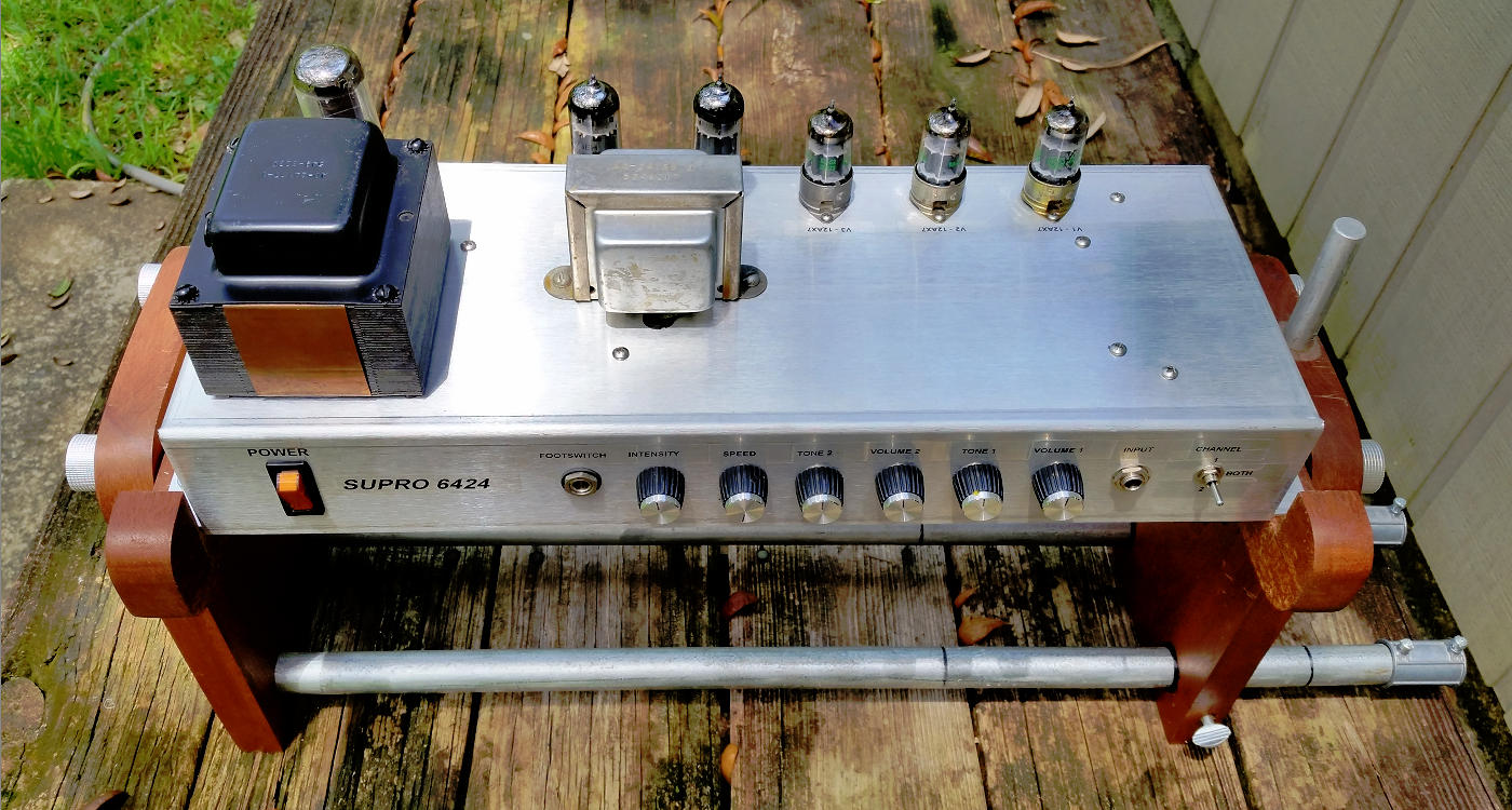
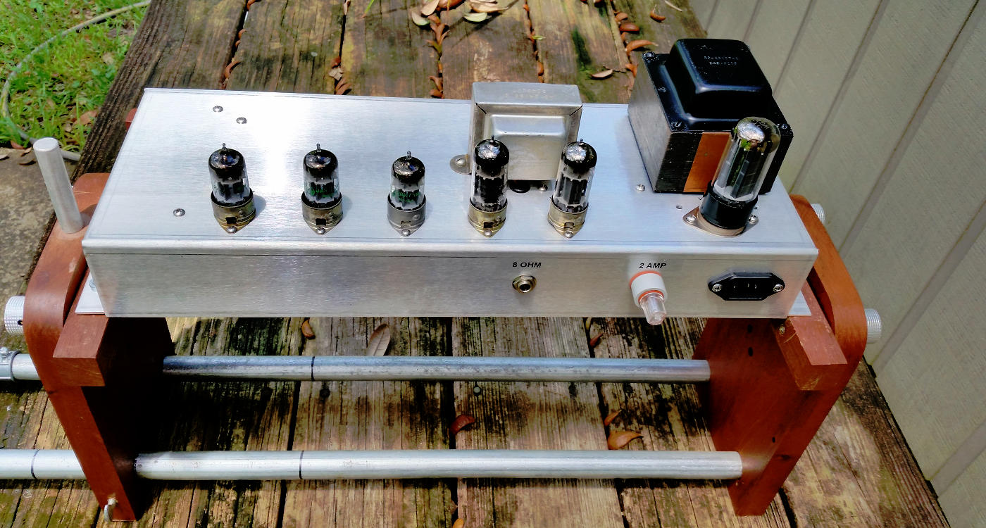
Done!
I did this short sound clip using my cell
phone. The actual sound is brighter than the recording suggests...
test.mp3 (1158KB)
And here's the schematic and layout...
supro.pdf (1.07M)
This amp works well with the more
affordable EL84s too... Supro_EL84.pdf (404KB)
And for those that don't care for
tremolo... Supro_no_trem (341KB)
Return to Index
|