|
updated May 10, 2014
1960 Vox AC-15
 In
the summer of 2012 Bnwitt started a discussion at Hoffman's Amp forum. He
proposed to build a 1960 Vox AC-15 for his studio. His idea was to develop a
layout for a single chassis, Marshall style amp. The unique vibrato circuit of
this amp has intrigued me for a long time. Soon I was caught up in Barry's idea
and began corroborating with him on this project. We swapped many ideas back and
forth, but soon realized we were headed two different directions. He wanted to
use two boards and keep a similar tube layout and control panel layout kinda
like the original, but put it all on a single chassis. I liked the idea of one
single board, tubes lined up across the back like a Marshall, and rearrange the
faceplate to fit the board layout. Barry soon became busy with his real life and
dropped off the forum. I don't know if he ever completed his project, but he's
to blame for my interest in the AC-15. I completed my layout but set it aside
and got busy with house remodeling and planning my retirement at the end of the
year. The AC-15 idea had faded. In
the summer of 2012 Bnwitt started a discussion at Hoffman's Amp forum. He
proposed to build a 1960 Vox AC-15 for his studio. His idea was to develop a
layout for a single chassis, Marshall style amp. The unique vibrato circuit of
this amp has intrigued me for a long time. Soon I was caught up in Barry's idea
and began corroborating with him on this project. We swapped many ideas back and
forth, but soon realized we were headed two different directions. He wanted to
use two boards and keep a similar tube layout and control panel layout kinda
like the original, but put it all on a single chassis. I liked the idea of one
single board, tubes lined up across the back like a Marshall, and rearrange the
faceplate to fit the board layout. Barry soon became busy with his real life and
dropped off the forum. I don't know if he ever completed his project, but he's
to blame for my interest in the AC-15. I completed my layout but set it aside
and got busy with house remodeling and planning my retirement at the end of the
year. The AC-15 idea had faded.
Then this winter lego4040 contacted me with some questions
about my layout drawings. He was excited about building this amp. He helped me
refine the layout by pointing out some inconsistencies between the different
drawings and in doing so, inspired me to revive my own interest. And when I saw
his board come to life from my drawings, I was hooked. I had said I was through
building amps, but here I go again. Lego, it's really your fault!
My original design incorporated a Fender style cap board and doghouse. One
day while playing Visio, I realized I could use one dual cap can, stretch the
main board a little bit, and eliminate the separate cap board, and still have a
clean layout. This idea became the final plan and is what I used to build my
amp.
This was to become my most ambitious project to date. For
a seemingly simple amp, the 1960 Vox AC-15 has a higher parts count than any amp
I've built. And my logical but unproven layout required more planning than my
other projects. The jam packed board had to be right and have a logical flow for
component locations. And there are a lot of jumpers that must be in the right
places too.
The board layout, tube lineup, and control panel had to
fit together as a unit. All other components were arranged to accomodate this
unit. Slowly it came together on screen. I really enjoy the planning phase, but
the actual construction has a lot of tangible rewards mainly because now you
begin to see and feel your project and you know it's real.
Even though the circuit remained true, the layout design
stepped way out of the Vox box and I remained cautiously skeptical right to the
end. But all that went away when I finally flipped the switch. A few preliminary
voltage checks and I was wailing away in under 5 minutes. The amp is quiet when
it should be and sounds nice when you're playing. The tremolo is very deep and
smooth and rivals the Fender
harmonic tremolo in my Revibe. And the Vibrato is really a true pitch shifting
vibrato, although it only has a single modulation stage and is not as intense as
I would like. It sounds very nice,
but not as nice as my Magnatone M10-A dual stage vibrato. The Vibrator channel
is brighter than the Normal channel. The Normal
channel has that nice EF86 sound that you would expect. It's also much louder
than the Vibrator channel.
So, all that planning paid off. The layout is a proven
winner. I'm really pleased with the way this project turned out.
The following pics appear in the same order as the build progressed. Enjoy...
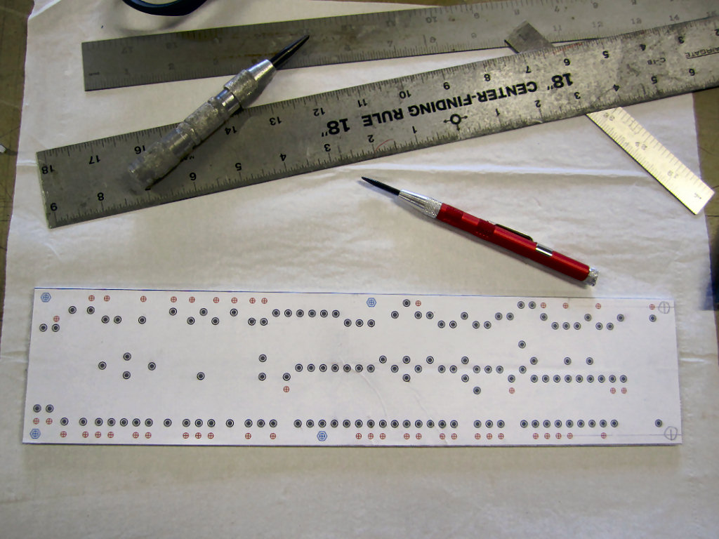
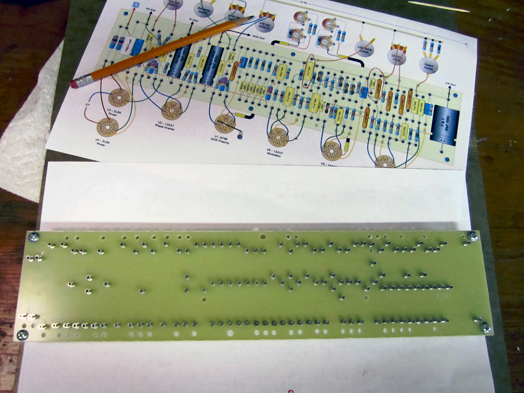
The drill guide is taped to the board using double sided
carpet tape. It's ready to be center punched and drilled. There are a lot of
holes on this board and it can be confusing concerning which hole is for what. I
drill the larger standoff holes (blue) to proper size first, then switch to a
1/8" bit to drill the wire passthru holes (red). Finally, I use a 3/32" bit to
drill all the turret holes.This method works well for me and when I start
loading the turrets if I accidently put a turret in a wire passthru hole I will
know immediately because it will be a sloppy fit.
The board has been drilled and now it's time to load the
turrets. Notice the turret holes are smaller than the wire passthru and standoff
holes.
Turrets are installed using a drill press and staking tools
available from Hoffman.
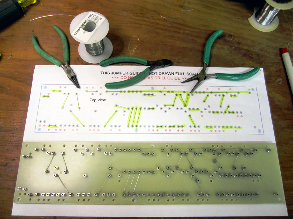
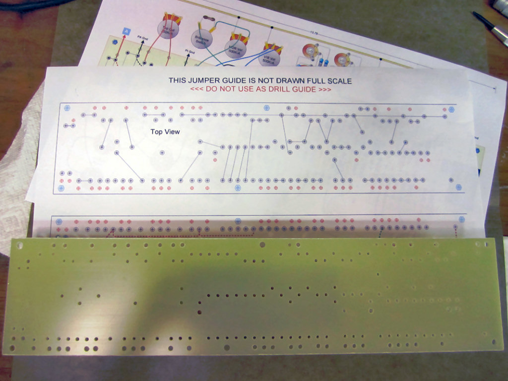
Lot of jumpers on this board. I use a highlighter to mark the
jumper guide as I go.
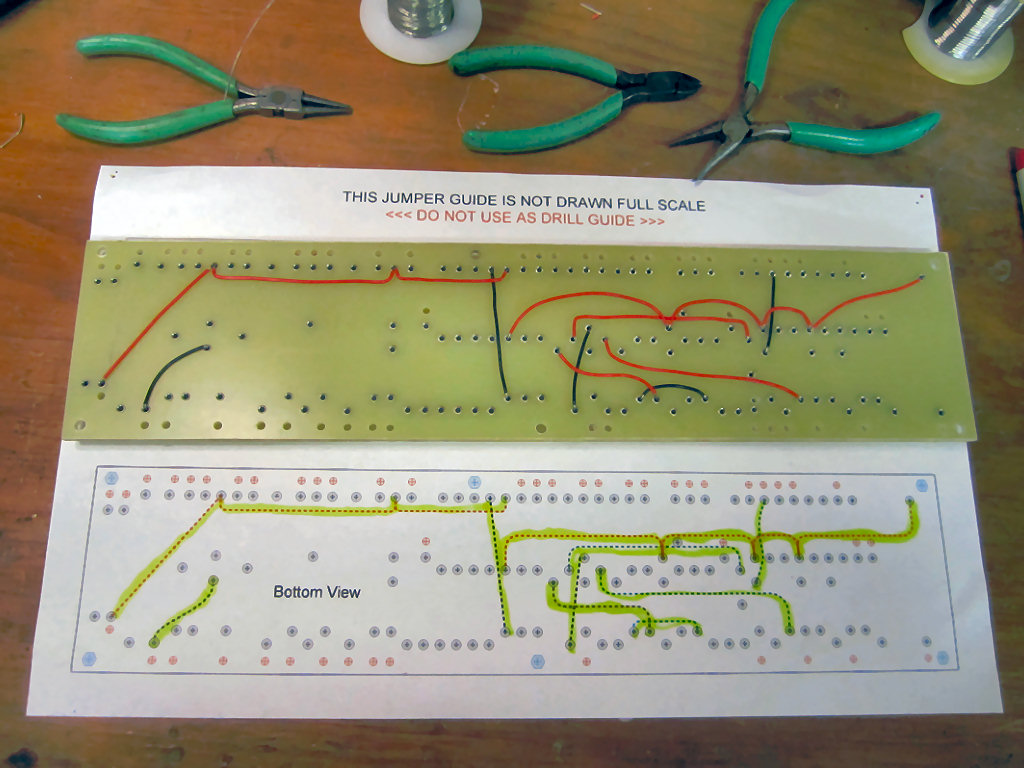
Same for the underboard jumpers. A mistake here will cause a
lot of grief later on.
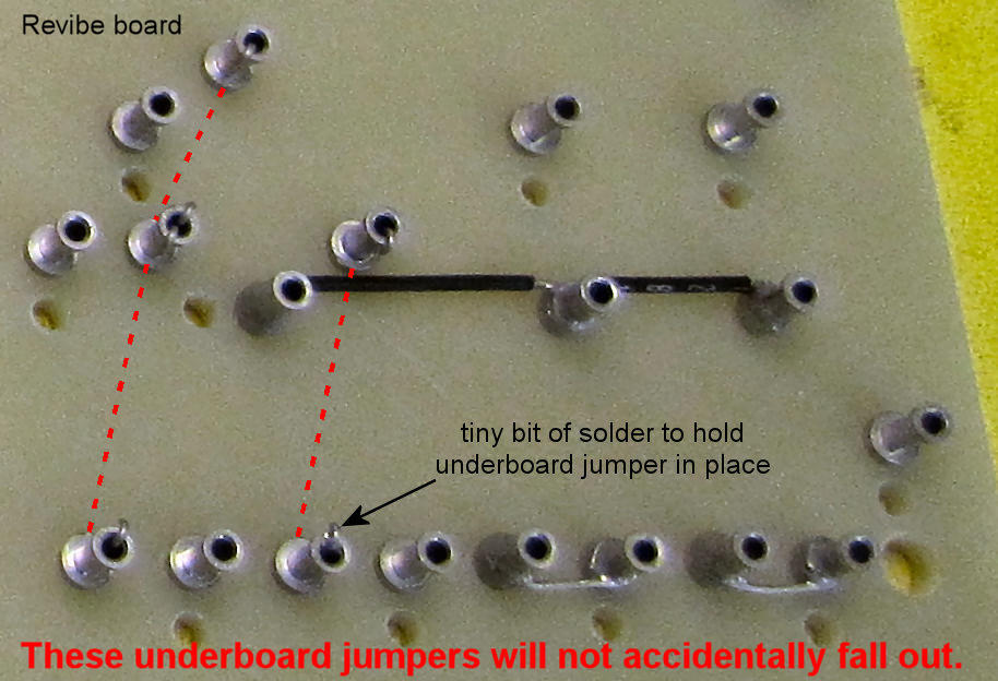
I don't like using underboard jumpers but sometimes it's
unavoidable with a complicated board. When I do use them I want to know they
will stay in place securely. So, I always push the end of the jumper completely
through the turret and 'hook' the end back over the outside of the turret. This
little detail allows you to see the jumper even after soldering, but more
important, it prevents the jumper from falling out of the turret whenever you do
any later soldering.
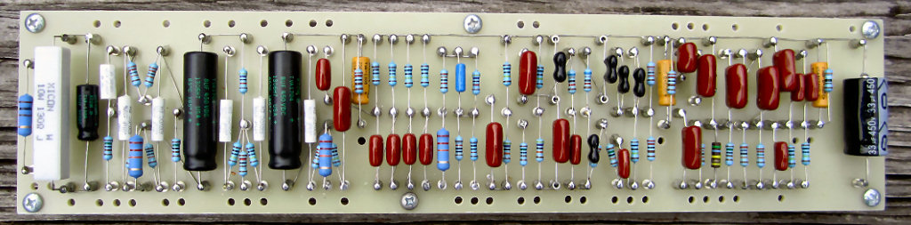
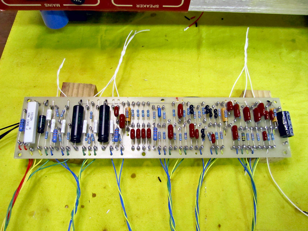
And here's the loaded board. I sure hope it's right!
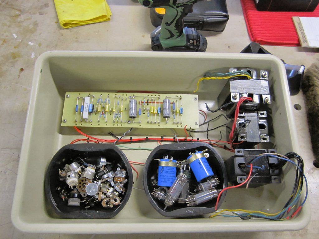
My Matchless Lightning became a donor for this project. A lot of these parts
will go into the AC-15 chassis.
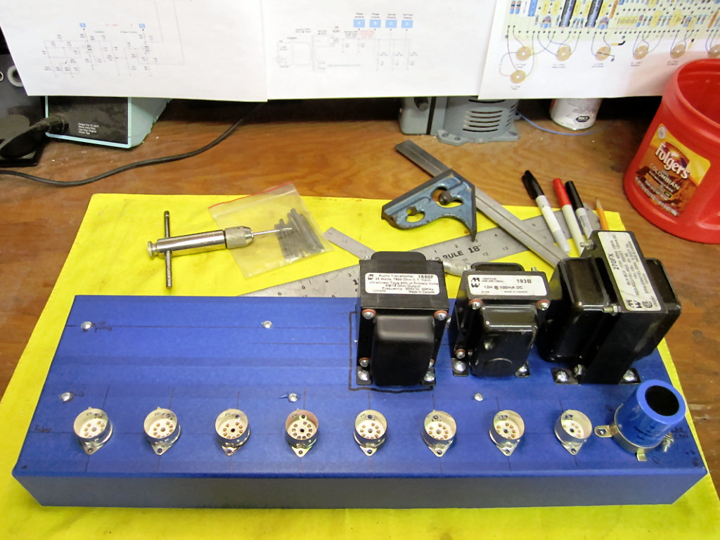
I got the chassis from turretboards.com. It's thick enough
that I was able to tap with 4-40 and 6-32 to secure the tube sockets and cap
clamp. Most of the drilling is done for the top of the chassis.
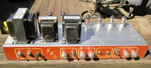
Beginning to look kinda Marshally now.
Rear panel is drilled and components fitted.
And the front panel is drilled and loaded. I even have a poor
man's faceplate. Looks like an amp now.
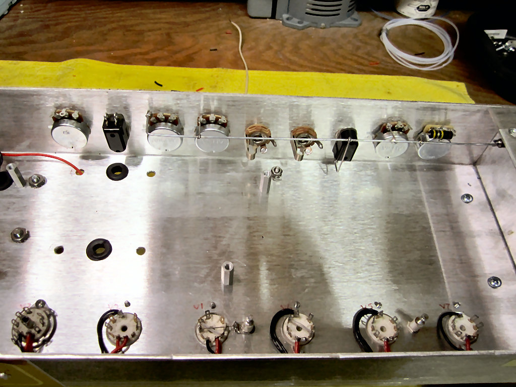
Filament string wiring comes next.
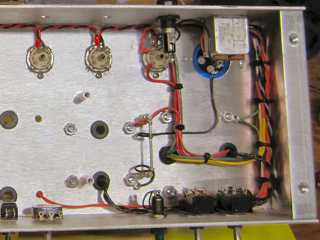
And the power supply is wired and has been tested at this
point. Notice the ground buss.
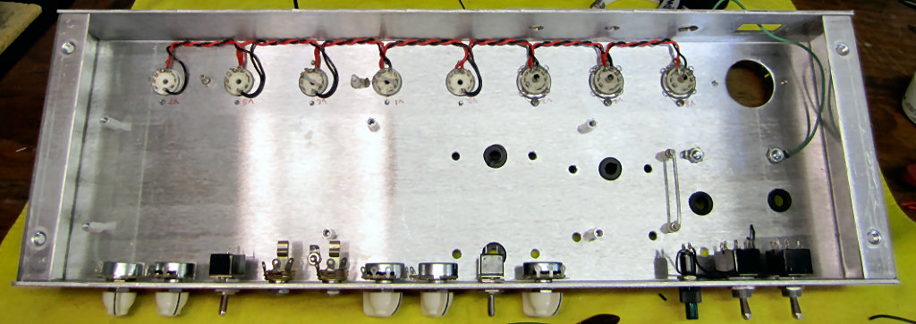
The ground buss for the control panel has been installed. It
will attach to chassis with a lug directly under the input jacks.
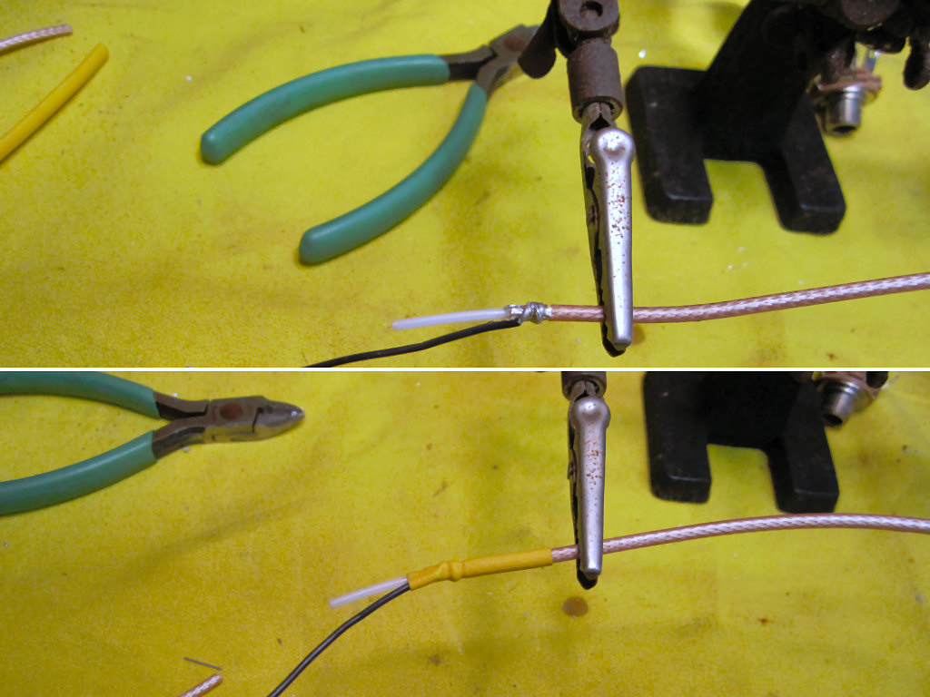
I like to use RG-316 for input connections. The PTFE
insulation make it very easy to work with. Don't try this with RG-174.
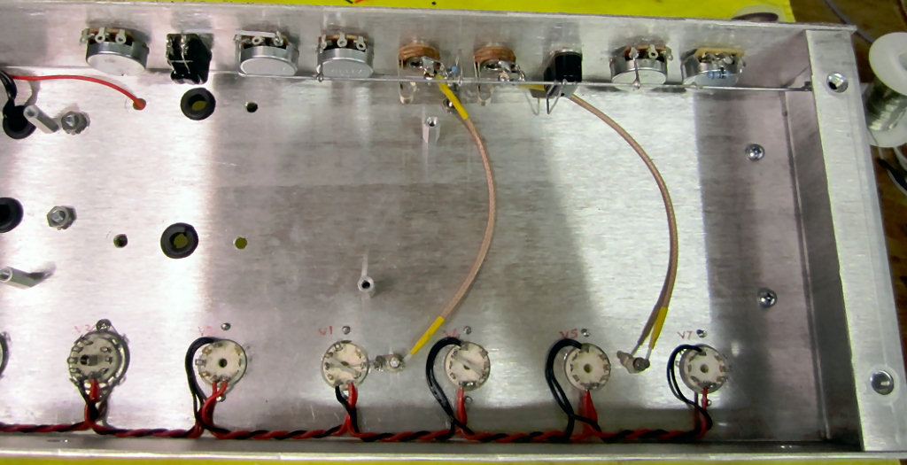
The input jacks are connected. Next the OT was installed but
I forgot to take a picture.
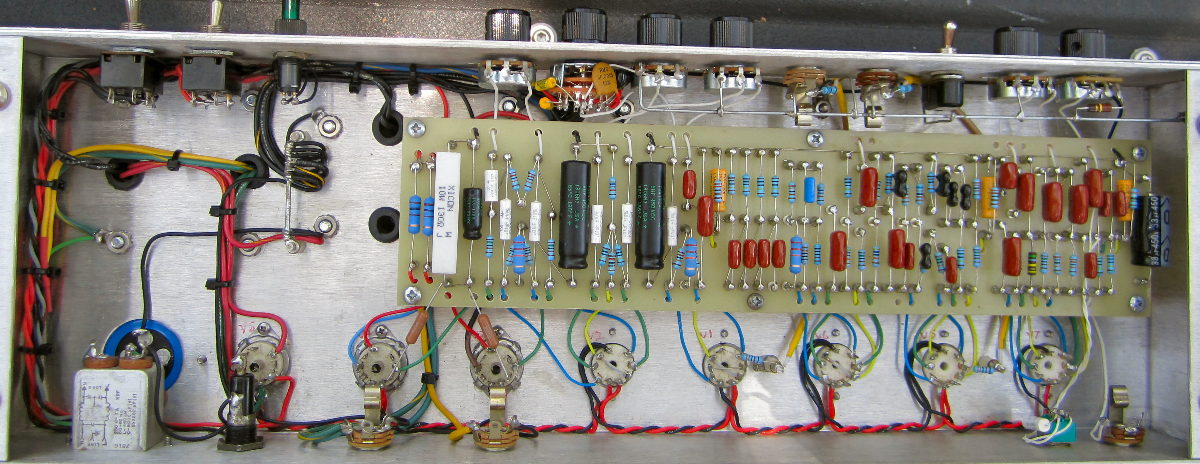
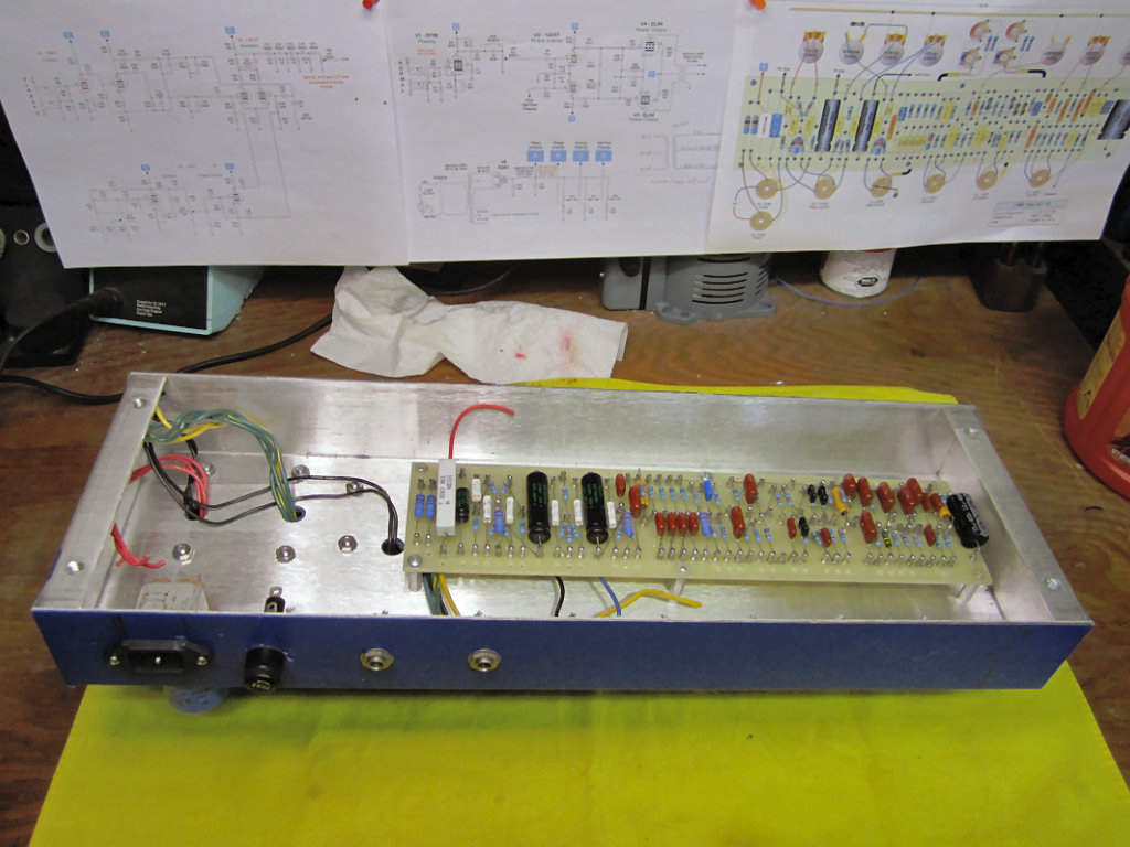
The interconnecting wires are in place and the board is ready
to be permanently installed.
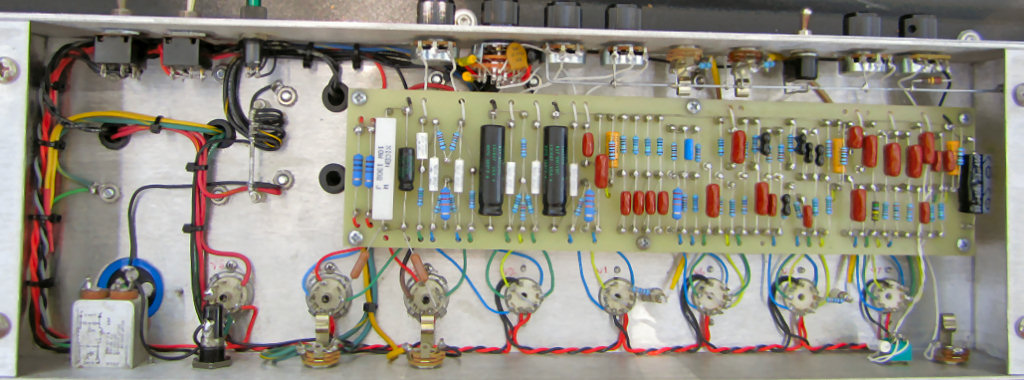
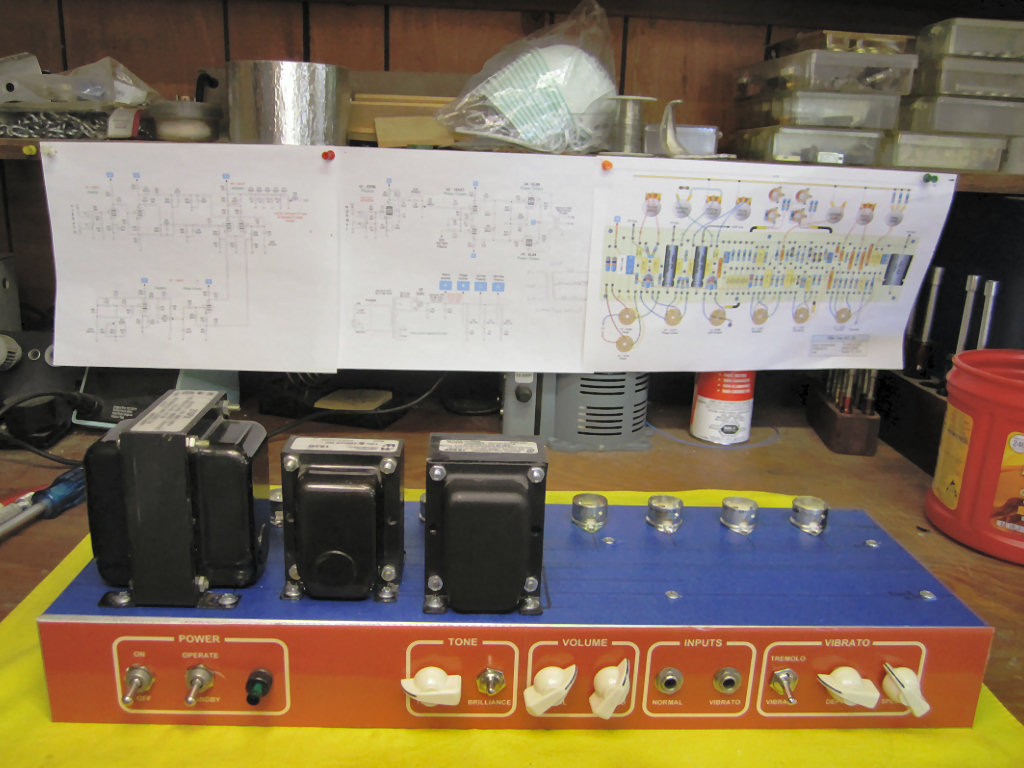
Done! (Click for a closeup view)
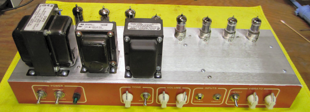
Front view.
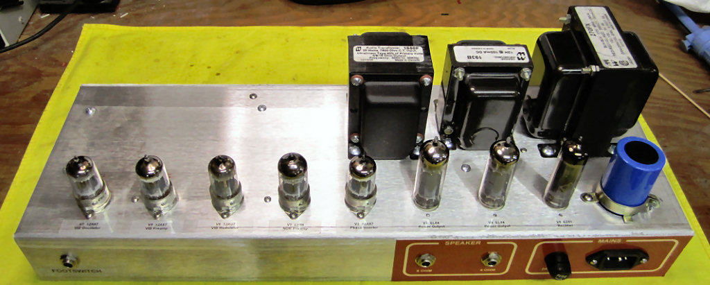
Rear view.
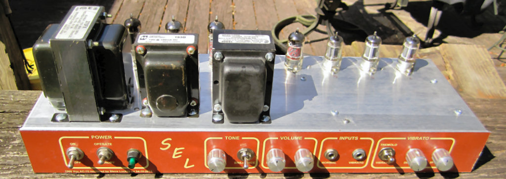
Thanks to Ed I actually have a real faceplate. That's a first
for me! I had to lose the chicken heads because they were too close and were
constantly fighting.
Download my full size board layout, drill
guide, jumper guide, ground scheme, schematic, and more in a single PDF.
Vox AC15.pdf (914KB)
These mods are a nice addition to the stock
AC-15. I have tested all of these on my amp.
Vox_AC15_mods.pdf (324KB)
Return to Index
|