|
March 16, 2013 The Revibe, 6G15 reverb plus 6G12 vibrato
The unit is very quiet. The reverb sounds great! Way over the top surfer stuff! And rich sound when used in moderation, which is how I like it. I'm not really sure how to describe the sound of the vibrato. It's not a pitch shifter, but it has a richness that I can only say makes the typical tremolo sound pale and one dimensional by comparison. This is by far the best tremolo I've ever heard. I highly recommend this project for anyone into reverb and/or tremolo. Once again, I started on the drawing board with the layout, working strictly from Doug's schematic. His board was too long to work in my plan so I rolled my own with Visio. I really enjoy this part of the project. I spent a long time working on the board design. (Measure twice, cut once kinda mentality. You really don't want to mess it up at this phase.) There's a lot of stuff to consider. My board worked out to be 12" x 3 1/8". This size works great in a 17" chassis and gives a comfortable amount of space for other components. Makes interconnecting wiring a breeze. I've come to love this layout style. I'll never do tweed again! I cut the chassis to 17" length because I wanted the reverb tank to sit on the chassis. Worked perfect for the layout I was after. The 8Ω reverb input jack is located near the power supply end of the chassis and the sensitive Hi Z reverb output lay just a couple inches away from the recovery stage. Very convenient. After it was up and running, I added the blinky LED and made a few minor changes. Other than that, it's just like Doug's schematic. Here's a list of my changes...
I'm really pleased with the way this project turned out. The walnut end caps are the only dressing it will get. I rather look at this stuff than hide it in a pretty box. Here are some pics...
Download the latest revision of my schematic, full size board layout, and drill guide in a single PDF. Several of these changes do not appear in the photos above but all changes are incorporated into my Revibe. revibe.pdf (1.3MB) (Revised 12/06/2016) |
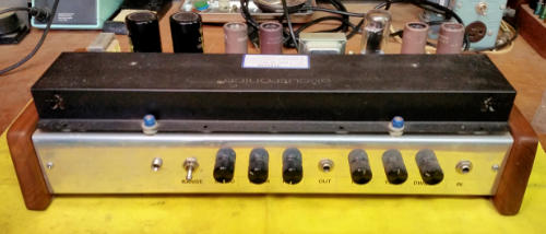 I've
been intrigued with Doug's Revibe project ever since I first read about it
several years ago. And then I was reinspired when he built a rack version. I
always knew I'd have to build it some day. Well, some day is here! I built it in
the same style as my Warbler. It all fits nicely in a 17" x 6 1/2" x 2 1/2"
chassis.
I've
been intrigued with Doug's Revibe project ever since I first read about it
several years ago. And then I was reinspired when he built a rack version. I
always knew I'd have to build it some day. Well, some day is here! I built it in
the same style as my Warbler. It all fits nicely in a 17" x 6 1/2" x 2 1/2"
chassis.


