|
February 10, 2007 November Project from AX84.com
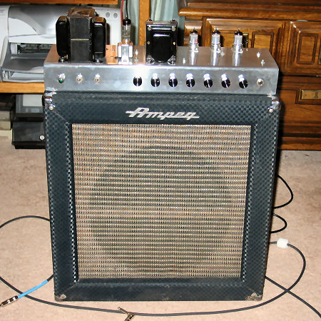
It didn't take long to realize I was not the first to have this idea. Randall Aiken and the guys from www.ax84.com had already designed and revised exactly what I was wanting to do. So, rather than reinvent the wheel, I used their schematic to create my board layout. I scrounged the iron and tubes from an old '50s Fisher mono amp/tuner that was driving a pair of EL84s. The choke was leftover from my TDR amp upgrade. The $25.00 chassis came from eBay. And I had enough sockets, switches, and jacks. So, a couple small orders from Hoffman and Mouser and I was ready to go. The build went surprisingly fast with no stumbling (except for a reversed diode). I must say that it was a joy to work inside this style chassis. All my other recent builds have been inside a tweed style chassis. Very tedious work in cramped corners! The sound is much tamer than the 18 Watt tremolo when using fixed bias and NFB. Kinda sparkly clean with my Strat. It does have a lot of grind and distortion when cranked, though. Perched on top of the MarsPeg and plugged into a 15" Eminence Big Ben. I have no intentions of building a cab. I've totally run out of floor space! I'm pleased with the results and had a hoot building it. My addiction is fed once more!
|
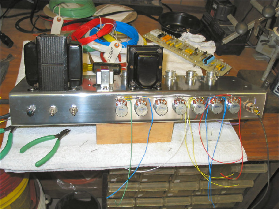 Wiring the pot harness is much easier with the pots temporarily mounted on the outside of the chassis. No need for special jigs that must have the same precise layout. Making connections to the pots is much easier and everything will line up perfectly since I'll use the same mounting holes when I flip the pots. |
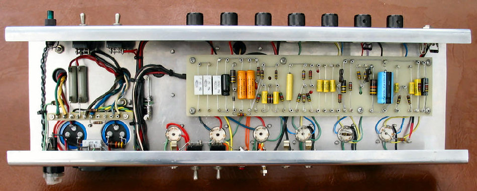 Completed chassis. It's done! Notice the bias diode is now properly orientated. My donor power transformer leads were too short to 'fly' directly to the proper connections, so I built a small turret strip rather than splice leads. The filament leads on this old PT are the actually windings. The HV winding puts out too much B+, hence the 250Ω power resistors on the left. I may put a Hammond 270FX in this chassis later. |
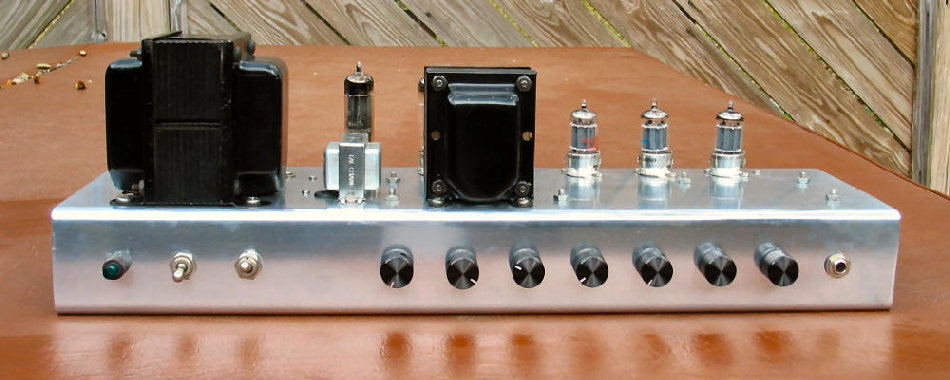 Full frontal view. I still like the contrast of the black anodized aluminum knobs (from Mouser) against the bare chassis. Control panel layout, left to right is: indicator, power, standby, presence, master volume, bass, middle, treble, bright volume, dark volume, and single input. The input is internally jumpered to the separate bright and dark preamps. |
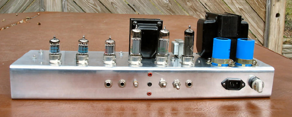 Rear panel view shows a simple interface. Layout, left to right is, preamp out, power amp in, bias adjust, bias test points, bias switch (fixed or cathode), NFB on/off, speaker jack, IEC power connector, and indicating fuse holder. |
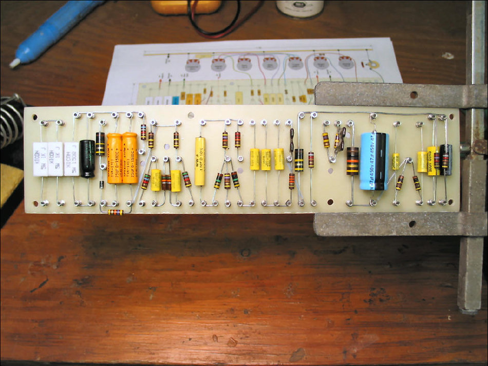
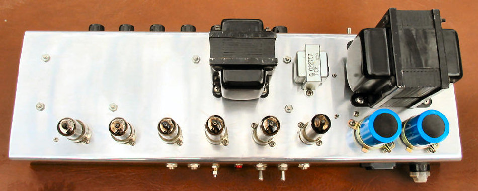 Top view. No surprises. Simply clean and traditional Marshall style layout. Download the schematic and full size board layout. (november.pdf, filesize = 329k) |
 After building the MarsPeg, actually a
Marshall 18 Watt tremolo amp housed in an Ampeg cab, I had an idea.... I
think I'd like to experiment with the basic Marshall 18 Watt design, maybe
put a 1987 Plexi front end on the EL84 power amp. Add some NFB and a
presence pot. Maybe even use fixed bias.
After building the MarsPeg, actually a
Marshall 18 Watt tremolo amp housed in an Ampeg cab, I had an idea.... I
think I'd like to experiment with the basic Marshall 18 Watt design, maybe
put a 1987 Plexi front end on the EL84 power amp. Add some NFB and a
presence pot. Maybe even use fixed bias.